Search
Close this search box.

Quick Start Guide: LUGB Series Vortex Flow Meter Installation

Table of Contents

Vortex flowmeters are mainly used to measure gas, liquid, and steam. Before you buy a vortex flowmeter, you must consider Vortex Flow Meter Installation. In addition to understanding the guide for vortex flowmeter installation, it is more important to understand the requirements of vortex flowmeters for pipelines. For example, upstream and downstream straight pipe sections, pipeline pressure, pipeline vibration environment, etc.

Installation Environment

Please note that although the following content is cumbersome, it summarizes our Sino-Inst vortex flowmeter installation experience. It is recommended that you read it before purchasing a vortex flowmeter.

Vortex Flowmeter with integrated temperature and pressure compensation to measure steam flow

The installation site should not have strong vibration and strong magnetic interference. Pipeline vibration caused by pumps or valves will cause measurement errors. In severe cases, it may even affect the normal measurement of the vortex flowmeter.

Avoid the direct influence of high-temperature heat sources and radiation sources. If installation is necessary, insulation and ventilation measures must be taken.

When measuring high-temperature media such as steam, insulation treatment should be performed to prevent the converter from overheating. Ensure that the vortex flowmeter housing is exposed to the outside so that heat can radiate outward to prevent the electronic components of the instrument from overheating and affecting the life of the flowmeter.

It is recommended that the vortex flowmeter body is not wrapped with an insulation layer to ensure the heat dissipation effect.

Vortex flowmeter installation with split temperature and pressure compensation

Avoid high-humidity environments and highly corrosive gas environments. If installation is necessary, ventilation measures must be taken.

Explosion-proof sensors and transmitters are installed in dangerous places, and safety barriers, display instruments, power supplies, computers, and other related equipment must be installed in safe places.

Sensors and transmitters should be reliably grounded. Explosion-proof ground wires must not be shared with the protective grounding of the strong power system.

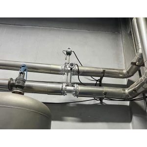
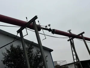
Vortex flowmeters should be installed as far as possible on long overhead pipelines. The sagging of the pipeline can easily cause leakage of the seal between the flowmeter and the flange. If it must be installed, the pipeline support points must be set at 2D upstream and downstream of the flowmeter.

The display of the vortex flowmeter is best installed indoors. When installed outdoors, attention should be paid to waterproofing, moisture-proofing, and sun protection. A protective cover can be used for sunshades.

Pay special attention to bending the cable into a U shape at the electrical interface to prevent water from entering the amplifier shell along the cable.

Vortex flowmeters should be installed near the valve outlet, otherwise, the opening and closing of the valve will affect the life of the flowmeter, and in severe cases, the flowmeter will be damaged.

For maintenance convenience, bypass pipes should be installed. Especially in some production processes where the fluid cannot be stopped in the middle.

Vortex Flow Meter installation

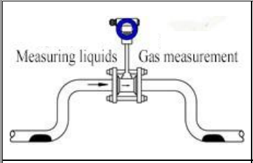
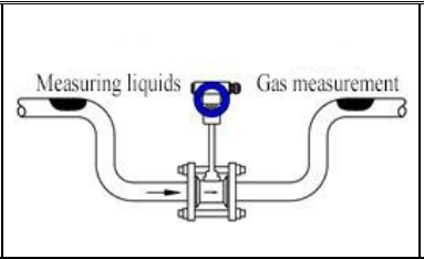
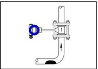
Please ensure that the medium in the pipeline is in a full pipe state. The flowmeter can be installed on a horizontal or vertical pipeline. If installed on a vertical pipeline, the measured medium must flow from bottom to top when it is a liquid.

A flow regulating valve should not be installed upstream of the flow meter but should be placed downstream.

Vortex Flow Meter Upstream and Downstream Requirements

Length Requirements for Upstream and Downstream Straight Pipe

The vortex flowmeter has certain requirements for the upstream and downstream straight pipe sections of the installation point. Otherwise, it will affect the flow field of the medium in the pipeline and the measurement accuracy of the instrument.

The requirements for the length of the upstream and downstream straight pipe sections of the instrument are as follows:

Vortex flow meter installation guidelines

The regulating valve should not be installed upstream of the vortex flow meter as much as possible. Instead, it should be installed 10D downstream of the vortex flow meter.

The inner diameters of the upstream and downstream piping should be the same. If there is a difference, the inner diameter of the piping Dp and the inner diameter of the vortex meter body Db. The following relationship should be satisfied: 0.98Db≤Dps1.05Db.

The upstream and downstream piping should be concentric with the inner diameter of the flow meter body. The misalignment between them should be less than 0.05Db.

The sealing gasket between the instrument and the flange. It cannot protrude into the pipe during installation, and its inner diameter should be 1-2m larger than the inner diameter of the meter body.

When measuring high-temperature and low-temperature media, attention should be paid to insulation measures. The high temperature inside the converter (inside the head housing) should generally not exceed 55℃.

Low temperature can easily cause condensation inside the converter, reduce the insulation resistance of the printed circuit board, and affect the normal operation of the instrument.

Different Installation Directions and Methods of Vortex Flowmeter

Vortex Flow Meters can be installed horizontally, vertically, or obliquely in pipes.

Vortex flow meter installation guidelines

On horizontal pipeline, when measuring gas,
if the measured gas contains a small amount of liquid,
the flowmeter should be installed at the higher part of the pipeline.

Vortex flow meter installation guidelines

On horizontal pipeline, when measuring liquid,
if the measured liquid contains a small amount of gas,
the flowmeter should be installed at the lower part of the pipeline.

On horizontal pipeline, when measuring liquid, if the measured liquid contains a small amount of gas, the flowmeter should be installed at the lower part of the pipeline.

On the vertical pipeline,when measuring the gas, the instrument is installed in the vertical pipeline, and the gas flow direction 1S unlimited.However.if there is a small amount of liquid in the pipeline,in order to prevent the liquid from entering the instrument measuring tube, the air flow should flow from bottom to top.When measuring the flow of liquid,the flow direction of liquid should be from bottom to top.

Wafer Flange Vortex Flowmeter

Wafer Flange Vortex Flowmeter

1. Spot weld the flange and the pipeline.
2. Remove the flow meter, weld the flange as required, and clean all protruding parts in the pipeline.
3. Install a sealing gasket with the same diameter as the pipeline in the inner groove of the flange. Install the flow meter into the flange. The flow direction indicator of the flow meter should be the same as the direction of the fluid. Then tighten it with bolts.

Insertion Vortex Flowmeter

Inserted Vortex Flowmeter

1. Use gas welding to open a circular hole slightly smaller than φ100mm on the pipeline. And remove the burrs around the circular hole. To ensure that the probe rotates smoothly.
2. Weld the flange provided by the manufacturer at the circular hole of the pipeline. The flange axis is required to be perpendicular to the pipeline axis.
3. Install the flange (ball valve) and sensor on the welded flange.
4. Adjust the screw so that the insertion depth meets the requirements. Ensure that the center axis of the probe coincides with the center axis of the pipeline. The flow direction of the fluid must be consistent with the arrow on the direction indicator.
5. Tighten the screws on the gland evenly. Note: The tightness of the gland determines the sealing degree of the instrument and whether the screw can rotate.
6. Check whether each link is completed well, and slowly open the valve to observe whether there is any leakage. If there is leakage, please repeat the previous step.

Split Type Vortex Flowmeter with Temperature and Pressure Compensation

Separate Vortex Flowmeter with Temperature and Pressure Compensation

The flow meter body is installed through a clamping flange or an integrated flange.
Attention should be paid to the installation design of the pressure measuring hole and the temperature measuring hole.
When the measured pipeline needs to install a temperature and pressure transmitter, the pressure measuring hole should be set at 5D downstream. The temperature measuring hole should be set at 6~8D downstream.

In summary, there are many factors to consider when installing a vortex flowmeter, such as performance, fluid characteristics, installation specifications, environmental impact, etc.

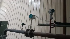
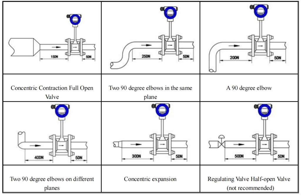
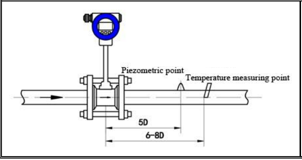
Generally, the flow caliber and the pipe diameter are required to be consistent and concentric. The length of the upstream straight pipe section usually depends on the form of the upstream resistance parts (reduction pipe, expansion pipe, elbow, valve). Generally, the length of the upstream straight pipe section must be 20D and the downstream 5D (where D is the pipe diameter).


Integrated-Vortex-Flowmeter-Applications


Sino-Inst provides a variety of vortex flowmeters, including those for measuring gas, liquid, steam, viscous media, etc., and supports customization of installation size, pressure range, temperature range, and liquid contact material. If you need to purchase a pressure transmitter or have any questions about the installation of a pressure transmitter, please contact our engineers!

Welcome To Share This Page:
Product Categories
Latest News
Get A Free Quote Now !
Contact Form Demo (#3)

Related Products

Related News

Vortex flowmeters are mainly used to measure gas, liquid, and steam. Before you buy a vortex flowmeter, you must consider

What is a vortex flow meter Vortex flowmeter is the only flowmeter that can measure all three-phase fluids (liquid, gas

Ideally, we should be able to use liquid volume sensors to directly measure the volume of liquid in a container.

Pressure Transmitter Installation can greatly affect the accuracy of pressure measurements. Pressure transmitter is an instrument used to measure the

Absolute Pressure Sensor or absolute pressure transmitter is what we often hear when choosing industrial pressure transmitters. So what is

Industrial Gas Flow Meters are instruments used to measure the flow rate, volume or mass of gas in pipelines. There

Scroll to Top

Get A Free Quote Now !

Contact Form Demo (#3)