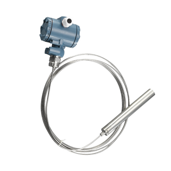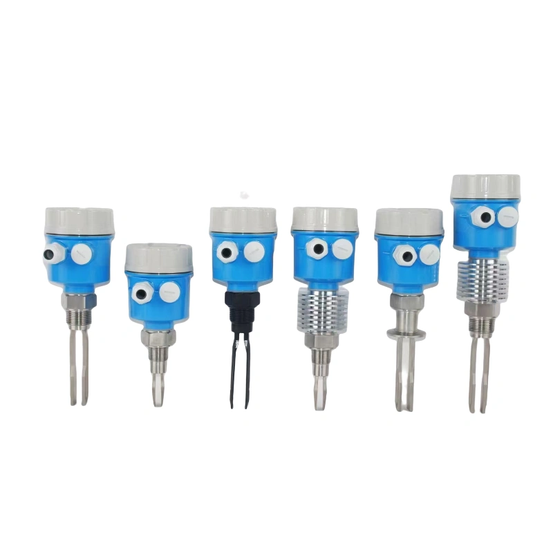
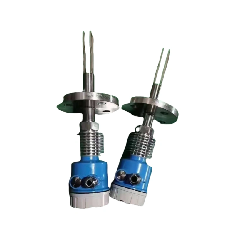
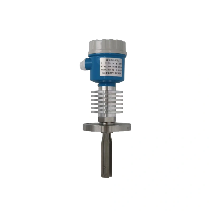
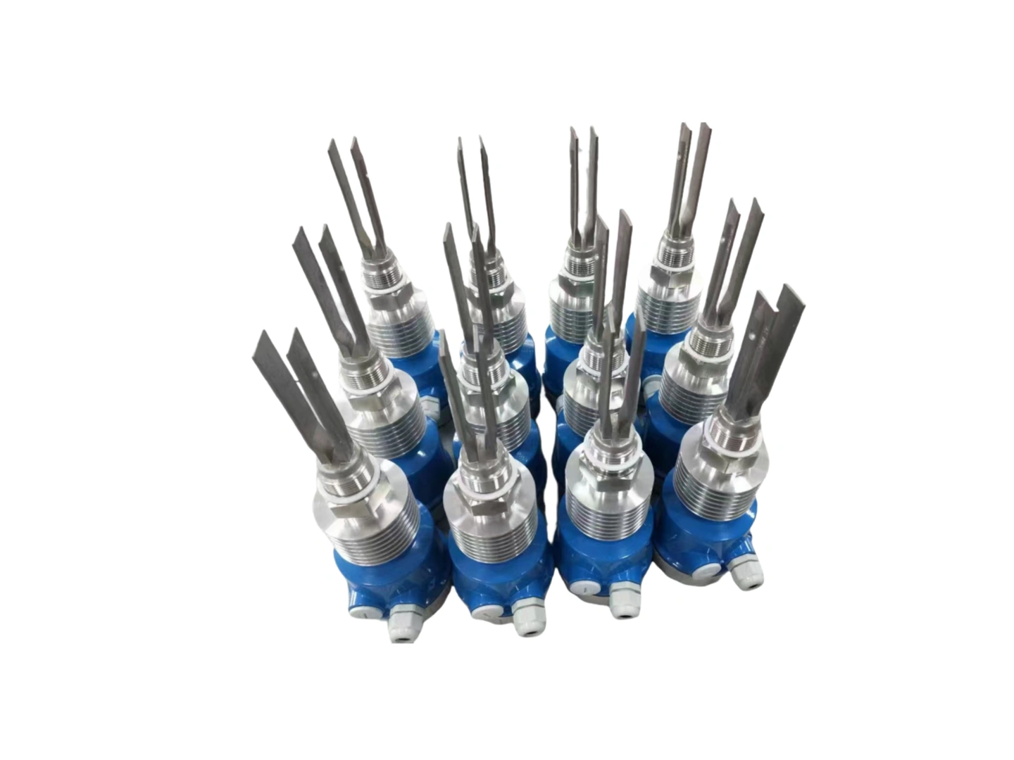
Working Principle of Tuning Fork Level Switches
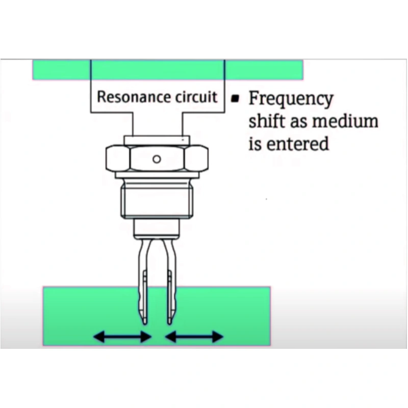
Ordinary tuning fork level switches have a pair of piezoelectric crystals. The piezoelectric crystal makes the tuning fork vibrate at a certain resonant frequency. When the tuning fork comes into contact with the measured medium, the frequency and amplitude of the tuning fork will change. These changes are detected by the intelligent circuit and converted into a switching signal.
The circuit board continuously monitors the frequency changes. It changes the output state to control the alarm, pump or valve. The circuit board is used to drive the tuning fork and generate a feedback signal to make the tuning fork resonate. When the tuning fork contacts the material, the tuning fork releases a feedback signal of a certain frequency. When the circuit detects a decrease in the signal frequency, the feedback signal is converted into the output of the contact signal.
The product relies on the damping effect generated by the medium covering the tuning fork to reduce the vibration frequency of the tuning fork and output a switching signal. Therefore, there is no need for a signal amplification circuit inside the product, which eliminates the trouble of frequently adjusting the sensitivity due to material changes.
Installation of Tuning Fork Level Switches
Installation location diagram
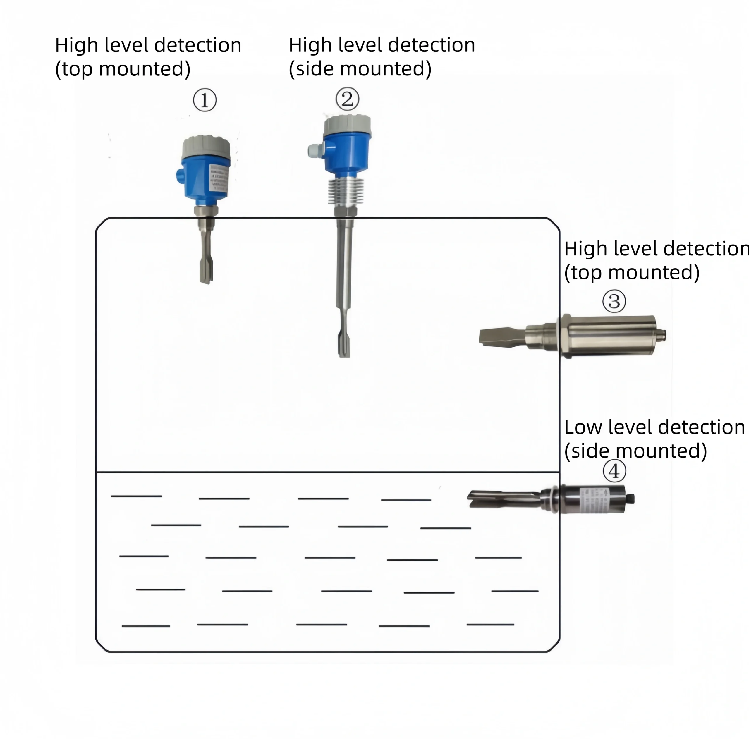
Tuning fork limit switch is usually installed side by side (installed on the side of the ware house wall) to detect the upper and lower limit positions of the material level height on the side wall of the warehouse body. When it is inconvenient to open holes on the side of the warehouse body, top mounting (installed at the top of the warehouse) can be used for installation, and the position should be selected to avoid material impact during feeding. It can also be installed on the pipeline to prevent the pump from running without material.
Installation diagram of storage tank:
Installation precautions
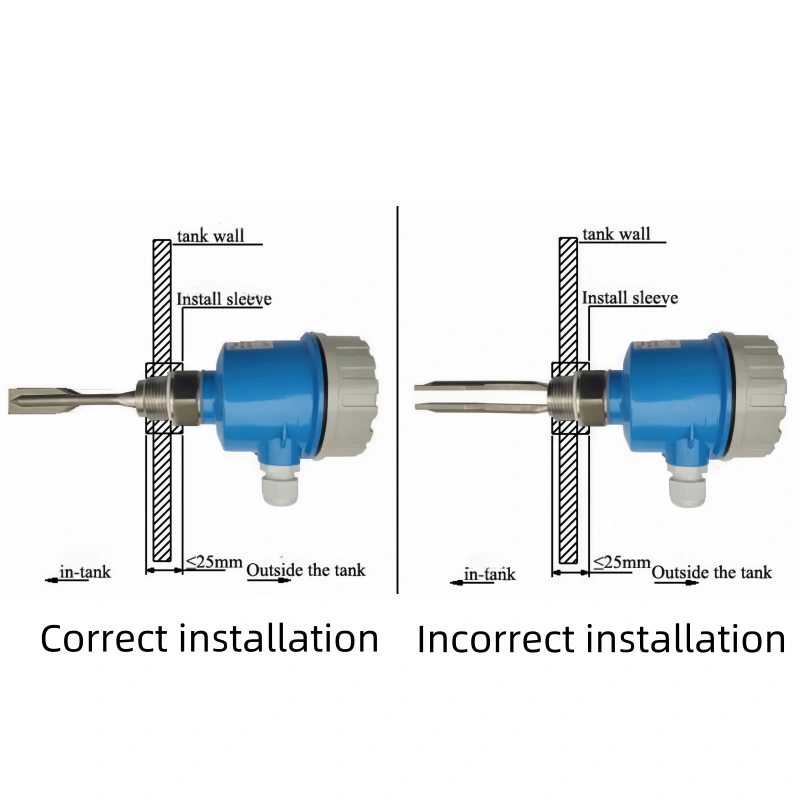
- Switch can be installed at an angle of 15-20 degrees horizontally downwards to reduce material impact and hangingphenomena.
- Try to stay as far away from the feed inlet of the barrel slot as possible to avoid material impact and false alarms. Ifunavoidable, a partition must be installed between the feeding port and the material level for protection
- A baffle (approximately 250mm in length and 200mm in width) can be installed above the level switch to preventimproper accumulation of materials around the level switch and reduce the impact of materials on the level switch
- When installing horizontally, the wire inlet of the junction box must face downwards, and the fixing nut of the powerwire inlet must be locked tightly
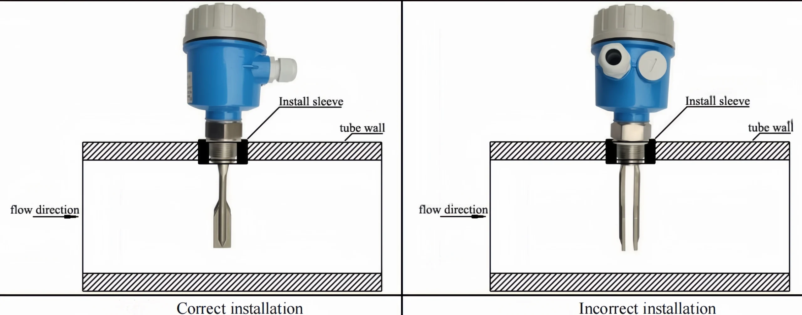
Pipeline inspection and installation diagram
Installation precautions
- When installing the sensor, insert it into the can body and tighten it by using a wrench to hold the hexagon on the upper part of the sensor thread. Be careful not to twist the junction box housing by hand, as tightening may cause rotatory between the junction box housing and the probe rod. The connecting cable between the electronic unit inside thehousing and the sensor is already connected when leaving the factory. Tightening the housing forcefully will cause the internal connecting cable to break.
- During installation and construction, be careful not to subject the fork body to strong impact to avoid damaging thepiezoelectric crystal.
- Instrument sensors should avoid the impact of materials as much as possible. When installed horizontally, the two parallel fork plates of the fork body should be perpendicular to the ground (at this time, the direction of the fork body should bemarked as up or down) to ensure that materials can easily flow out between the fork plates.