What is a flow orifice?
An orifice plate is a device used for measuring flow rate, for reducing pressure or for restricting flow (in the latter two cases it is often called a restriction plate). Either a volumetric or mass flow rate may be determined, depending on the calculation associated with the orifice plate. It uses the same principle as a Venturi nozzle, namely Bernoulli’s principle which states that there is a relationship between the pressure of the fluid and the velocity of the fluid. When the velocity increases, the pressure decreases and vice versa.
How does an orifice plate flow meter work?
A single-phase fluid filled with a pipe, when it flows through a throttle in the pipe, the flow will form a local contraction at the throttle, so that the flow rate increases and the static pressure decreases, so that a static pressure difference is generated before and after the throttle .
The greater the fluid flow rate, the greater the pressure differential produced, which indirectly measures the flow rate based on the measured differential pressure. This measurement method is based on the flow continuity equation (the law of conservation of mass) and the Bernoulli equation (the law of conservation of energy). The magnitude of the pressure difference is not only related to the flow rate but also to many other factors. For example, when the physical properties (density, viscosity) of the fluid in the form of the throttling device or the pipe are different, the pressure difference generated at the same flow rate is also different.
Orifice flow meter types
The classification of orifice flowmeters is mainly based on different pressure measurement methods and different orifice plates.
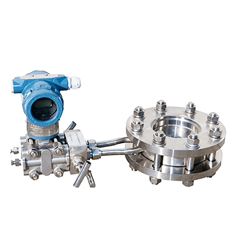
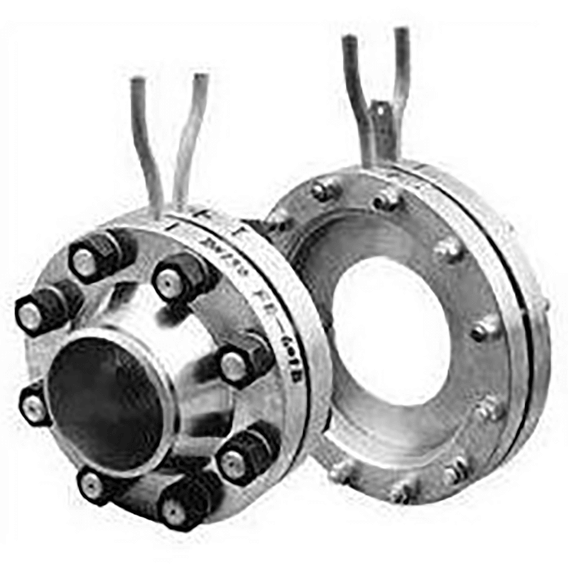
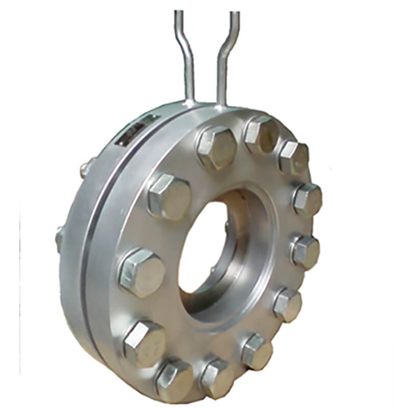
1. Standard orifice plate for pressure measurement in annular chamber: It is a standard orifice plate. Since the annular chamber pressure measurement is realized, the measurement accuracy is improved and the length of the small linear pipe section required during installation is shortened. It can be widely used in various departments.
2. Corner joints are individually drilled to take pressure from the standard orifice plate:
It is a standard orifice plate. This form is often used when the pipe diameter is above 400 mm. The pressure measurement methods include separate drilling of the flange, pressure measurement by a circular pressure equalizing ring, or pressure measurement by a square pressure equalizing ring. The orifice plate can be in the form of a shank hole or a non-standard round orifice plate, etc.
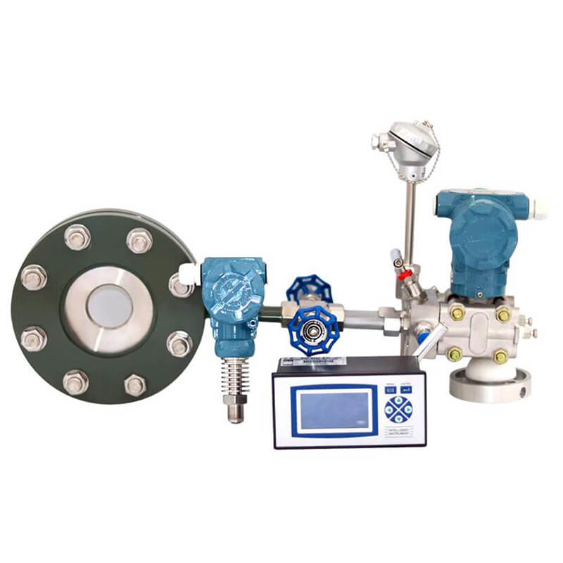
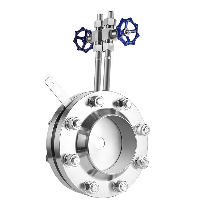
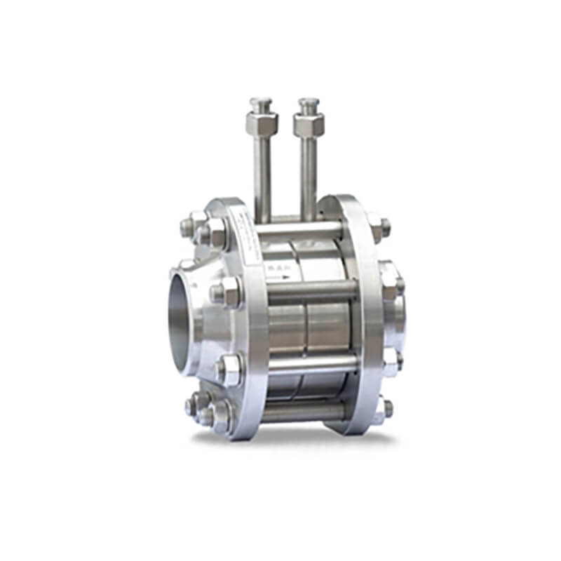
3. Flange pressure standard orifice plate: It is a standard orifice plate. Regardless of the diameter of the pipe, the centers of the upstream and downstream pressure holes are located 1 inch (25.5mm) away from the end faces on both sides of the orifice plate. This form is commonly used in oil refining systems.
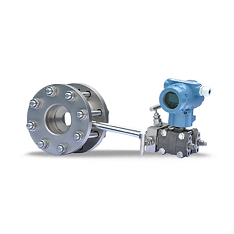
4. Standard orifice plate for diameter pressure measurement: It is a standard orifice plate. The pressure taking method is pipe pressure taking. The center of the upstream pressure tapping hole is located at one time the inner diameter of the pipe in front of the orifice plate. The center of the downstream pressure tapping hole is located half the inner diameter of the pipe from the rear end of the orifice plate.
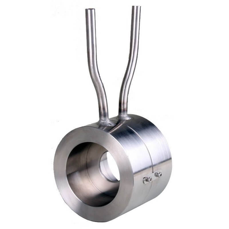
5. Small diameter orifice plate: It is a non-standard orifice plate. Used to measure fluids in pipe diameters from 10 mm to 50 mm.
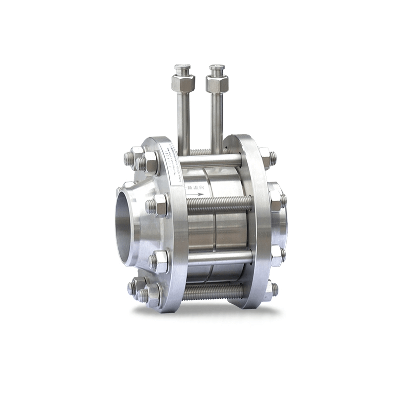
6. Double orifice plate: It consists of two standard orifice plates installed in a straight pipe at a certain distance from each other. According to the flow direction, the front hole is called the auxiliary orifice plate, and the rear hole plate is called the main orifice plate. The cross-sectional ratio m1 of the auxiliary orifice plate is greater than the cross-sectional ratio m of the main orifice plate. Two orifice plates form a nozzle with a liquid wall. It is used for flow measurement of low Reynolds number fluids or high viscosity.
7. Round orifice plate: It is a non-standard orifice plate, suitable for measuring the flow rate of fluids that are dirty, have bubbles, or contain solid particles, and their measurement accuracy is low.
8. Tapered entrance orifice plate: It is a non-standard orifice plate. The angle between the circular cone and the centerline is 45°. This tapered inlet orifice plate can be used in situations where the Reynolds number is very low, but the pipe size must not be less than 25 mm.
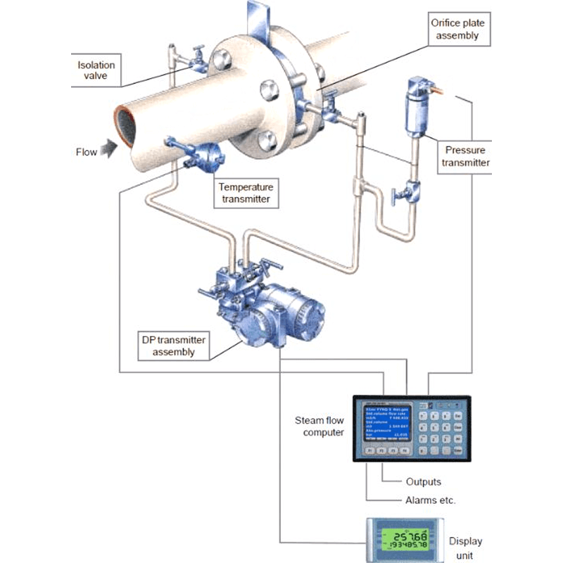
Orifice flow meter installation guidelines
1. Before installing the orifice plate, check whether the number and size of the throttling device meet the requirements of the pipeline installation location.
2. For newly installed piping systems, the pipes must be flushed and cleaned before installing the orifice plate.
3. Note that the orifice plate installation direction “H” corresponds to the inlet and “L” corresponds to the outlet.
4. The center of the orifice plate should coincide with the center line of the pipe, and the concentricity error shall not exceed the value of 0.015 (1/β-1).
5. When installing the orifice plate in the pipeline, ensure that its end face is perpendicular to the axis of the pipeline, and the verticality error shall not exceed ±1°.
6. The sealing piece used to clamp the orifice plate (including between the ring chamber and the flange, and between the ring chamber and the orifice plate) must not protrude into the inner wall of the pipe after clamping.
7. The orifice plate must be installed tightly and no leakage is allowed. Therefore, installation work must be carried out before pipeline pressure testing.
8. The pressure-conducting pipe should be laid vertically or inclined, and its inclination should not be less than 1:12. For fluids with higher viscosity, the slope should be increased. When the differential pressure signal transmission distance is greater than 3 meters, the pressure guiding pipe should be inclined in sections, and a gas collector and a settler should be installed at each highest point and lowest point.
9. In order to prevent the differential pressure signal from being transmitted incorrectly, the positive and negative pressure guiding pipes should be laid as close as possible, and antifreeze measures should be taken in severely cold areas. Electric heating or steam insulation can be used, but it is necessary to prevent the measured medium from overheating and vaporizing and generating gas in the pressure guiding tube to cause false differential pressure.
10. When the orifice plate is installed on the vertical main pipeline, the position of the pressure tapping port can be selected arbitrarily on the plane of the pressure tapping device. The orifice plate is installed in a horizontal or inclined main pipe, and the position of the pressure port is shown in Figure 4.
11. The pressure guiding pipe should be made of pressure-resistant and corrosion-resistant materials according to the properties of the medium being measured. Its inner diameter should not be less than 6 mm, and the length should preferably be within 16 meters.
12. There must be a certain length of straight pipe sections on the upstream and downstream sides of the orifice plate throttling device. Please consult the manufacturer for specific straight pipe section requirements.