Helical-Spiral Rotor PD Flow Meter Working Principle
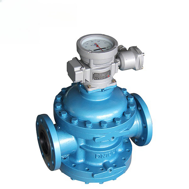
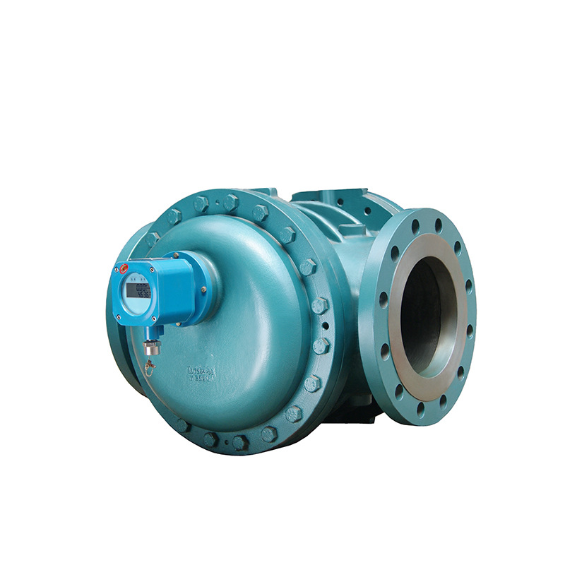
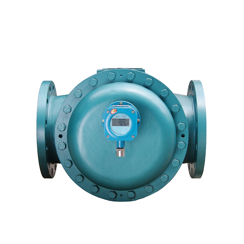
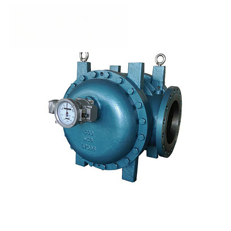
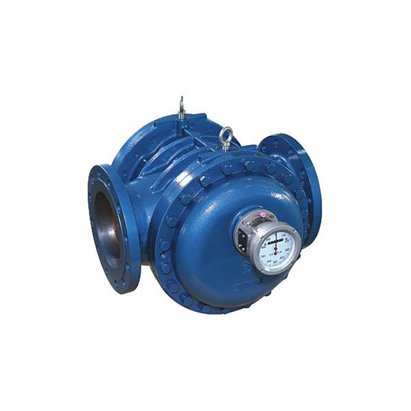
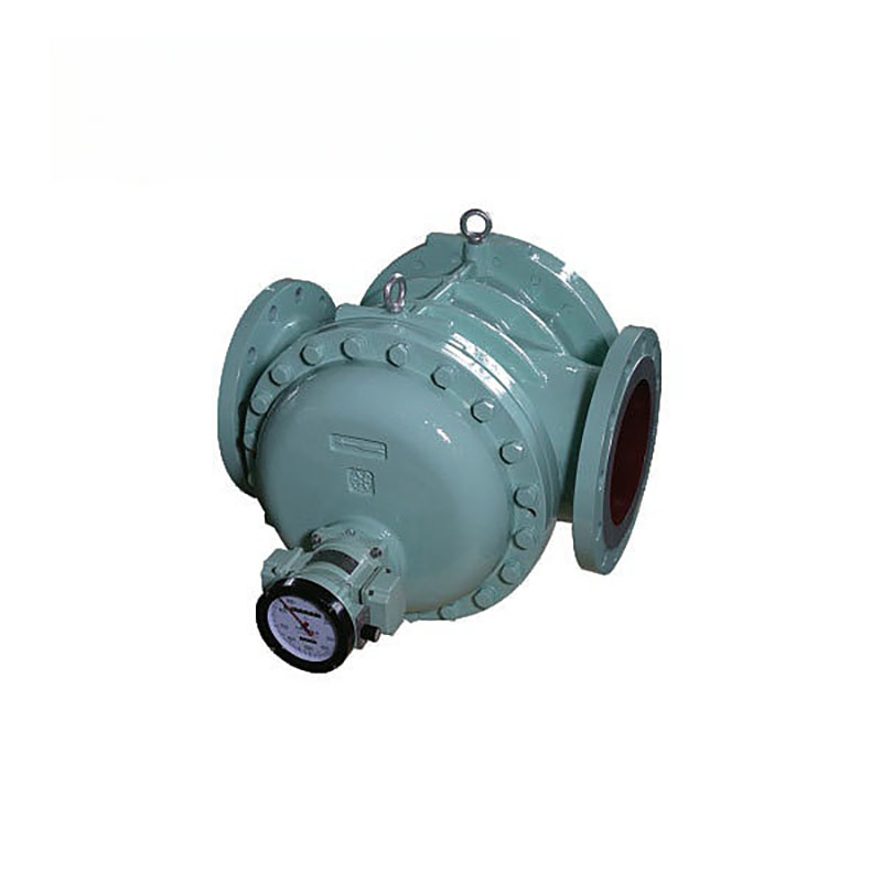
The LLT spiral rotor flowmeter consists of a flow transmitter and a counter. The main part of the transmitter is composed of a measuring chamber equipped with a pair of special toothed spiral rotors and a sealed coupling.
The counting mechanism includes a deceleration mechanism and an accuracy adjustment mechanism. The counter is a word wheel accumulation and an electric pulse transmitter, etc.
There is mainly a sealed cavity composed of a pair of special rotors and cover plates in the measurement chamber as the measurement unit of flow.
The rotor is driven by the pressure difference at the inlet and outlet of the flow meter to rotate. This continuously measures the liquid at the inlet and then sends it to the outlet through the sealed cavity.

The amount of liquid flowing through each revolution is eight times the seal chamber in the figure.
The total number of rotor rotations caused by the sealed coupling. And the speed of rotation is transmitted to the counting mechanism. There will be a pointer display and word wheel accumulation, and you can know the total amount of liquid passing through the pipe.
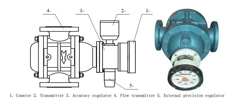
A pulse transmitter can also be installed in the counting mechanism to form a flow meter with transmitter. It can realize automatic measurement and control of remote transmission (quantification, accumulation, instantaneous and other functions).

