Search
Close this search box.
Turbine flowmeter with display
Turbine flowmeter side view
Turbine flowmeters
Flange Connection Digital Turbine Flow MeterFlange Connection Digital Turbine Flow Meter
Turbine flow meter flange connection
Turbine flowmeter explosion-proof housing
Turbine flowmeter with display
Turbine flowmeter side view
Turbine flowmeters
Flange Connection Digital Turbine Flow MeterFlange Connection Digital Turbine Flow Meter
Turbine flow meter flange connection
Turbine flowmeter explosion-proof housing

Flange Connection Digital Turbine Flow Meter for Liquids

Digital liquid turbine flow meter is based on the principle of torque balance and is a speed sensor. DN2~DN300, various standard flange connections can be configured.

1. High accuracy, generally up to ±1%R, ±0.5%R, high-precision type up to ±0.2%R;
2. Good repeatability. The short-term repeatability can reach 0.05%~0.2%. Frequent calibration or online calibration can achieve extremely high accuracy. It is the preferred flow meter in trade settlement;
3. It has three-point correction of the instrument coefficient, intelligently compensates for the nonlinearity of the instrument coefficient, and can perform on-site correction;
4. Input pulse frequency signal, used for total measurement and connection with computer, no zero point drift, strong anti-interference ability,
5. The range is wide, the medium and large diameters can reach 1:20, and the small diameters can reach 1:10;
6. Compact and lightweight structure, easy installation and maintenance, and large circulation capacity;

Digital Turbine Flow Meter Description

Flange Connection digital turbine flow meter is a velocity meter. It can be used to measure the volumetric flow and accumulation of low-viscosity, non-corrosive, clean liquids in closed pipelines.

The digital turbine flow meter is used in conjunction with the quantitative controller to achieve quantitative control, overflow alarm and other functions.

DN15~DN300, various standard flanges can be selected. Including German standard DIN, American standard ANSI, Japanese standard JIS, etc.

It can be widely used in petroleum, chemical industry, metallurgy, organic liquids, inorganic liquids, liquefied gas, city gas pipeline network, pharmaceutical, food, paper and other industries.

Digital Turbine Flow Meter Data Sheet

Implementation standards Turbine flow sensor (JB/T9246-1999)
Connection method Thread, clamp, flange, clamp-on type
Accuracy level ±1%R, ±0.5%R, ±0.2%R (need to be customized)
Sensor material 304, 316 stainless steel, etc.
Conditions of Use Medium temperature: -20℃~+120℃ Ambient temperature: -20℃~+60℃
Relative humidity: 5%-90% Atmospheric pressure: 86Kpa~106Kpa
Signal output function Pulse signal, 4-20mA signal
Communication output function RS485 communication, HART protocol, etc.
Working power supply External power supply: 24VDC±15%, ripple ≤±5%, suitable for 4-20mA output, pulse output, RS485, etc.
Internal power supply: 1 set of 3.6V10AH lithium battery, the battery voltage can work normally when the battery voltage is 2.0-3.0V
Signal line interface Basic type: Hausmann connector or built-in three-core cable; explosion-proof type, internal thread M20*1.5
Explosion-proof level Exia II CT or Exd II BT6
Protection level IP65 or higher can be customized

Flow Range

Nominal diameter Standard flow range Wide flow range Accuracy Class Max Pressure Drop
DN2mm 30~180L/h 1.00% 0.15Mpa
DN4mm 40~250L/h 40-400L/h 1.00% 0.12Mpa
DN6mm 100~600L/h 60~600L/h 1.00% 0.08Mpa
DN10mm 0.2~1.2m³/h 0.15~1.5m³/h 1%0.5% 0.05Mpa
DN15mm 0.6~6m³/h 0.4~8m³/h 1%0.5% 0.035Mpa
DN20mm 0.8~8m³/h 0.45~9m³/h 0.50%
DN25mm 1~10m³/h 0.5-10m³/h 0.50%
DN32mm 1.5-15m³/h 0.8~15m³/h 0.50% 0.025Mpa
DN40mm 2~20m³/h 1~20m³/h 0.50%
DN50mm 4~40m³/h 2~40m³/h 0.50%
DN65mm 7~70m³/h 4~70m³/h 0.50%
DN80mm 10~100m³/h 5-100m³/h 0.50%
DN100mm 20-200m³/h 10~200m³/h 0.50%
DN125mm 25~250m³/h 13~250m³/h 0.50%
DN150mm 30-300m³/h 15~300m³/h 0.50%
DN200mm 80-800m³/h 40~800m³/h 0.50%
DN250mm 120~1200m³/h 60~1200m³/h 0.50%
DN300mm 180~1800m³/h 90~1800m³/h 0.50%

Get Better Turbine Flow Measurement Solution

Sino-Inst is a manufacturer of digital liquid turbine flow meters. Has extensive experience in liquid flow measurement. Our Flange Connection Digital Turbine Flow Meter has good quality, better price!

Contact Form Demo (#3)
Products Categories
Get A Free Quote
Contact Form Demo (#3)

Digital Turbine Flow Meters Applications

Digital turbine flow meters require fluids that are clean, single-phase or low viscosity.

  1. Examples of commonly used fluids are as follows
    General fluids, including water, air, oxygen, high-pressure hydrogen, milk, coffee, etc.;
    Petrochemicals: gasoline, light oil, jet fuel, light diesel, naphtha, ethylene, polyethylene, styrene, liquefied gas, carbon dioxide and natural gas;
    Chemical solutions: ammonia, methanol, salt water, etc.;
    Organic liquids: alcohol, ether, benzene, toluene, xylene, butadiene, carbon tetrachloride, methylamine, acrylonitrile, etc.;
    Inorganic liquid: formaldehyde, anhydrous acid, caustic soda, carbon disulfide, etc.
    Regarding corrosive media, please consult us for selection.
    Currently, the bearings of most turbine flowmeters are spherical bearings, which have high requirements for the cleanliness of the measured medium. If the medium contains particulate impurities, the bearings will wear out quickly. If there are fibrous impurities, they will wrap around the turbine blades and affect the normal rotation of the turbine. In practical applications, an effective filter should be installed upstream of the turbine flowmeter.
  2. Turbine flow meter for diesel fuel measurement
    When measuring diesel, you can generally choose a liquid turbine flowmeter for measurement.
    Why are liquid turbine flowmeters suitable for measuring diesel fuel? Liquid turbine flow meters have high anti-electromagnetic interference and anti-vibration capabilities. Furthermore, it has a wide range. Not only small and medium diameters can be measured, but also large diameters can be measured.
    Liquid turbine flow meters can be divided into flange connection type, thread connection type, plug-in type and clamp type sanitary type according to the installation method. The specific installation method needs to be selected based on on-site selection.
  3. Turbine flowmeter measures water
    Turbine flow meters are also a good choice when you need to measure water flow.
    Perhaps, you would say, electromagnetic flowmeter is a better choice. Yes, in most cases, we will choose electromagnetic flowmeter to measure water flow. But if the electromagnetic flowmeter cannot measure. For example, raw water, non-conductive aqueous solution, etc. Then, we can consider using a turbine flow meter.
Flange Connection Digital Turbine Flow Meter for Liquids Detail Display
More Detail

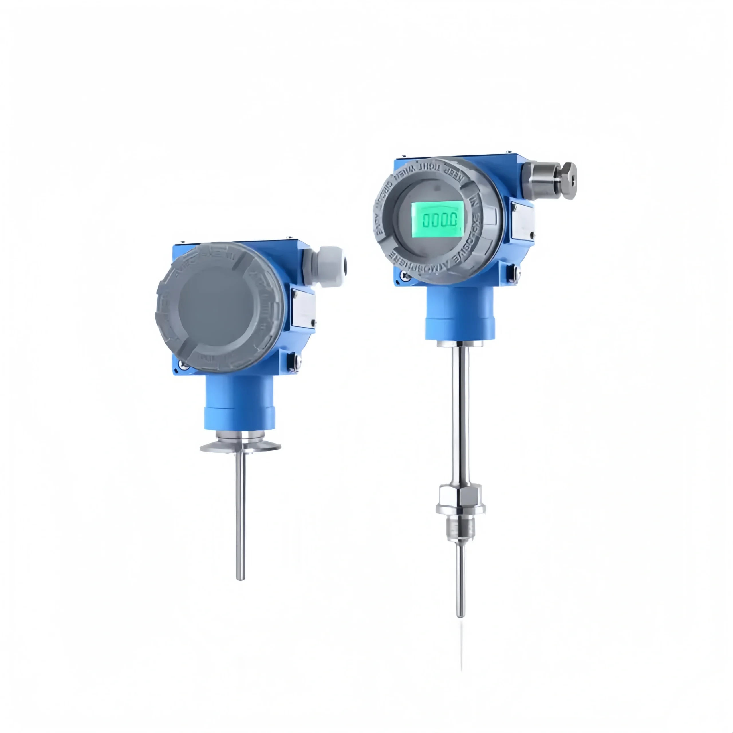
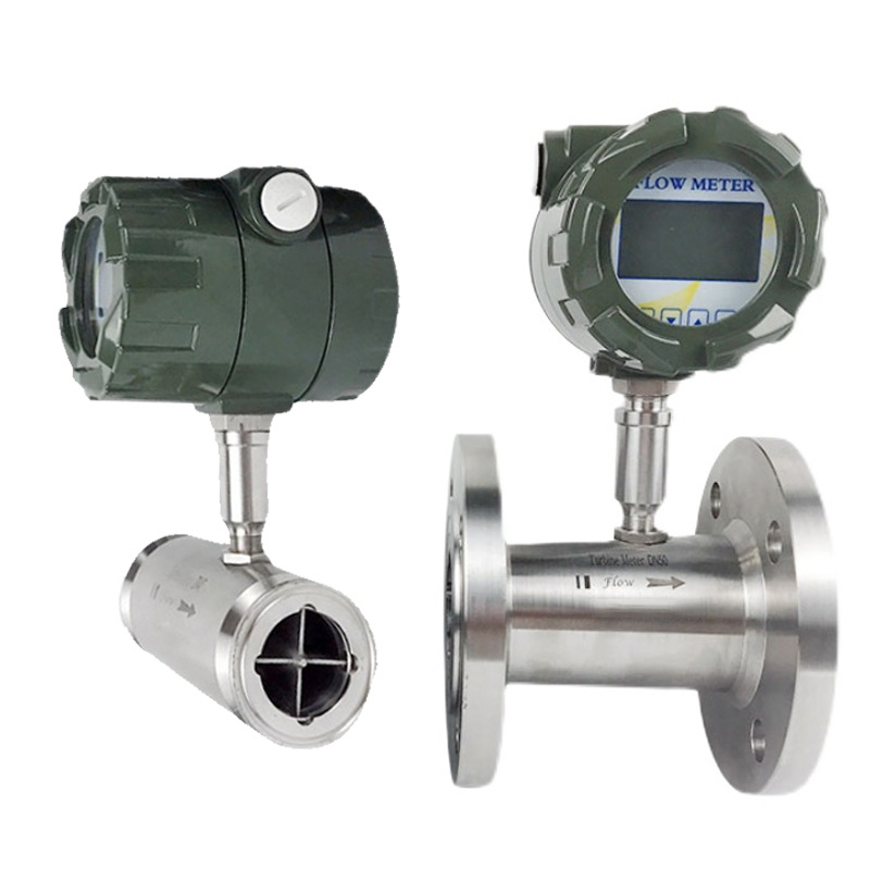
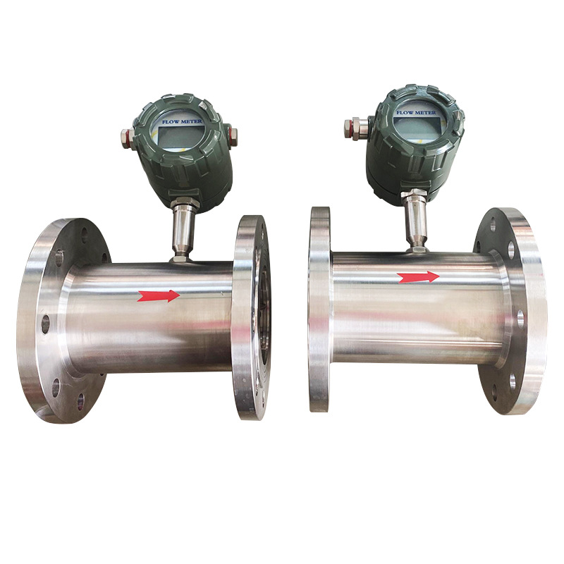
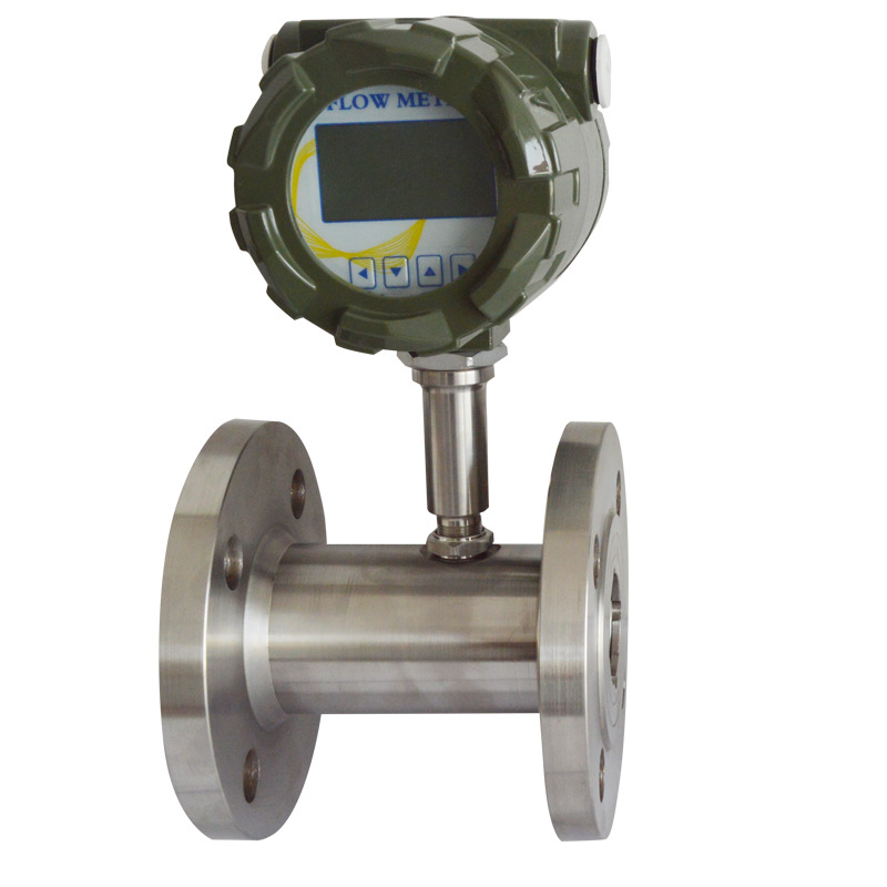
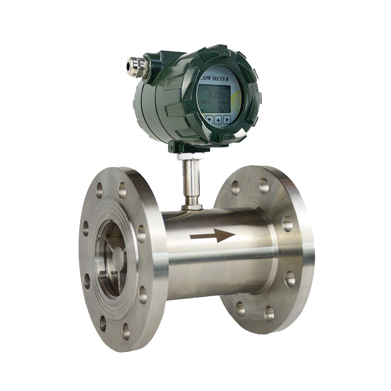
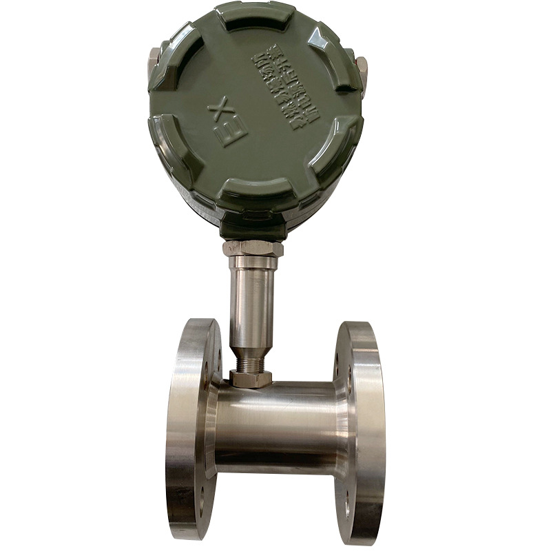
Digital Turbine Flow Meter Installation Guidelines

  1. Installation location
    The pipe must be completely filled with liquid. It is important to keep the pipe completely filled with liquid at all times, otherwise the flow display will be affected and measurement errors may result.
    Avoid air bubbles. If air bubbles enter the measuring tube, the flow display may be affected, possibly causing measurement errors.
  2. Required length of upstream and downstream straight pipe sections
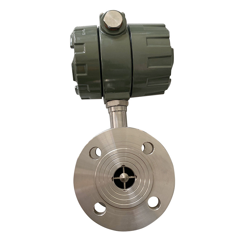
    Turbine flowmeters are sensitive to flow velocity distribution distortion and rotational flow in the pipeline, and the turbulent flow entering the sensor should be fully developed. Therefore, necessary straight pipe sections or rectifiers must be equipped according to the type of flow obstructions on the upstream side of the sensor. The required straight pipe section lengths at the inlet and outlet sections are as follows:
    In general, the straight pipe section of the inlet section is >10DN, and the straight pipe section of the outlet section is >5DN;
    90° elbow, inlet straight pipe section > 20DN, outlet straight pipe section > 5DN;
    Two 90° elbows on the same plane, the straight pipe section at the inlet section is >25DN, and the straight pipe section at the outlet section is >5DN;
    Two 90° elbows on different planes, the straight pipe section at the inlet section is >40DN, and the straight pipe section at the outlet section is >5DN;
    Shrink pipe, the straight pipe section of the inlet section is >15DN, the straight pipe section of the outlet section is >5DN;
    Pipe expansion, the straight pipe section of the inlet section is >20DN, the straight pipe section of the outlet section is >5DN;
    Fully open valve, inlet straight pipe section >20DN, outlet straight pipe section>5DN;
    Semi-open valve, inlet straight pipe section >50DN, outlet straight pipe section>5DN;
  3. Precautions for pipeline installation
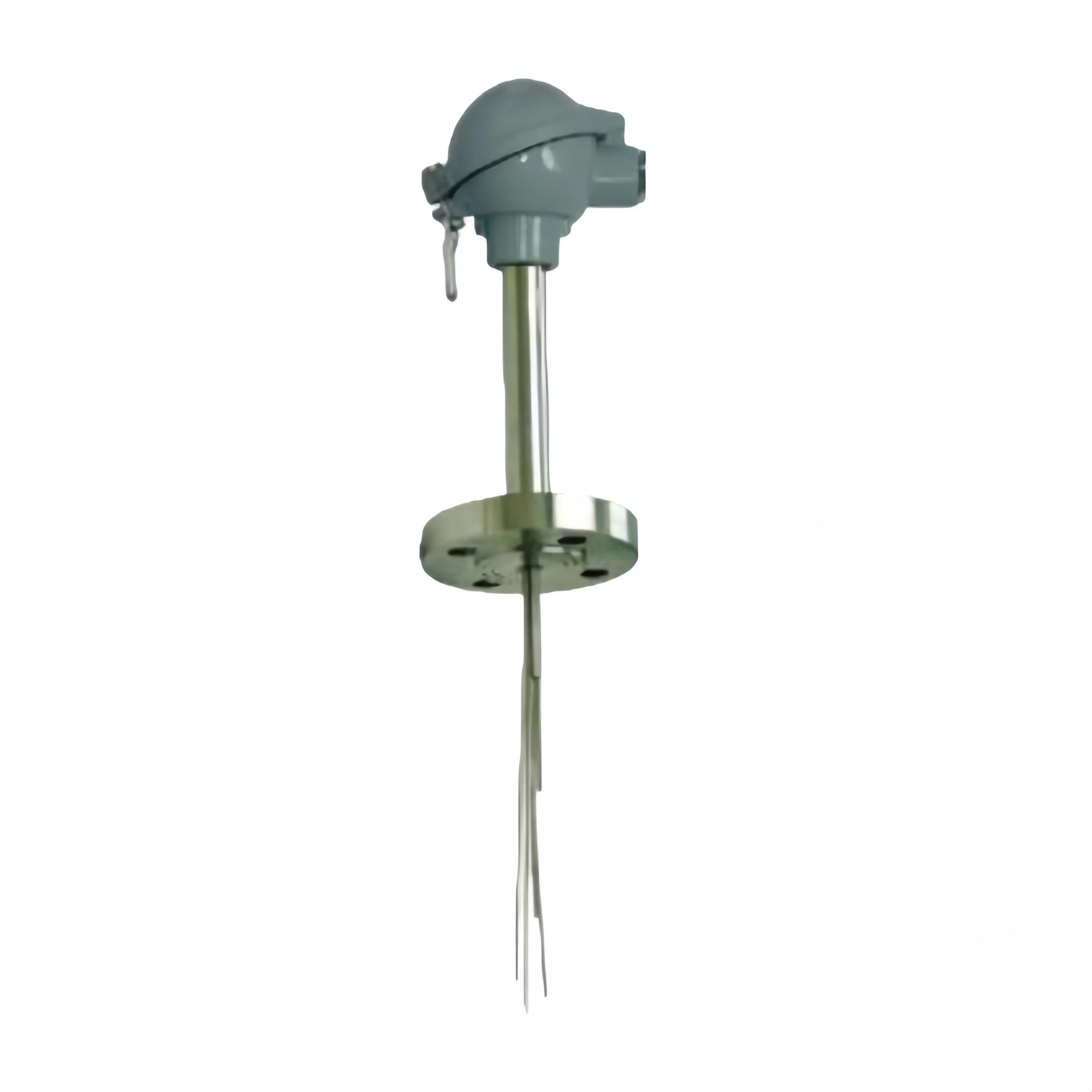
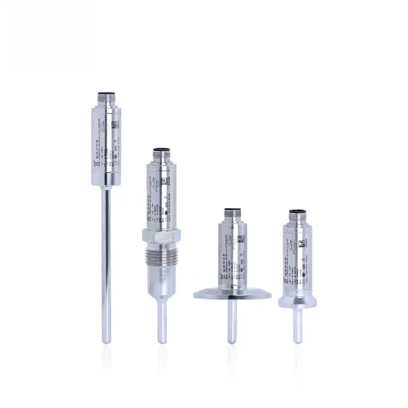
    The sensor should be installed in a place that is easy to maintain and has no vibration in the pipeline, strong electromagnetic interference and heat radiation.
    Horizontally installed sensors require that the pipeline should not have a visually detectable inclination (generally within 5°), and vertically installed sensors should also have vertical deviations of less than 5°. In places where the flow cannot be stopped, a bypass pipe and a reliable stop valve should be installed. Make sure there is no leakage in the bypass pipe when measuring.
    At the location where the sensor is installed in the newly laid pipe, a short pipe is first connected to replace the sensor. After the “cleaning” work is completed and the pipe is clean, the sensor is officially connected.
    If the fluid contains impurities, a filter should be installed on the upstream side of the sensor, and the pipeline should be regularly cleaned and discharged to remove precipitated impurities; if the measured liquid contains gas, a gas eliminator should be installed on the upstream side of the sensor. The drain outlet and air outlet of the filter and air eliminator should lead to a safe place.
    When the sensor is installed outdoors, measures should be taken to avoid direct sunlight and rain.

Related Products

Related News

Scroll to Top

Get A Free Quote Now !

Contact Form Demo (#3)