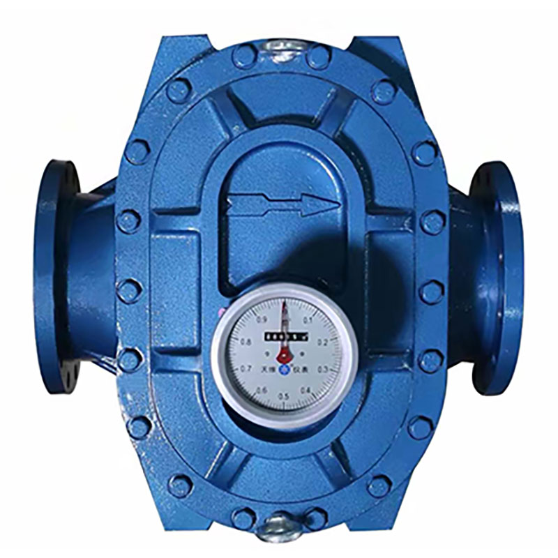
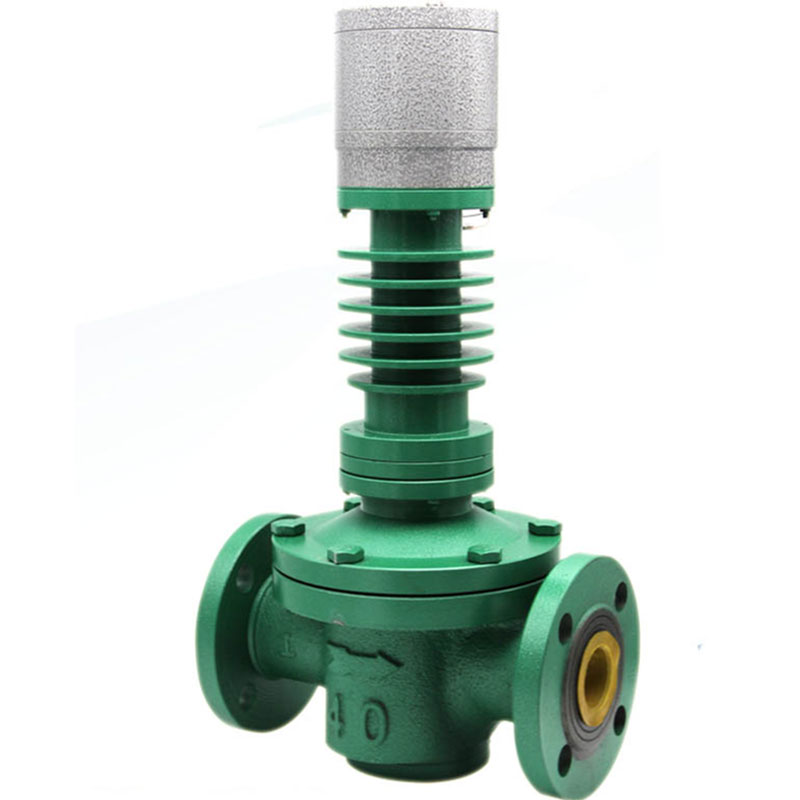
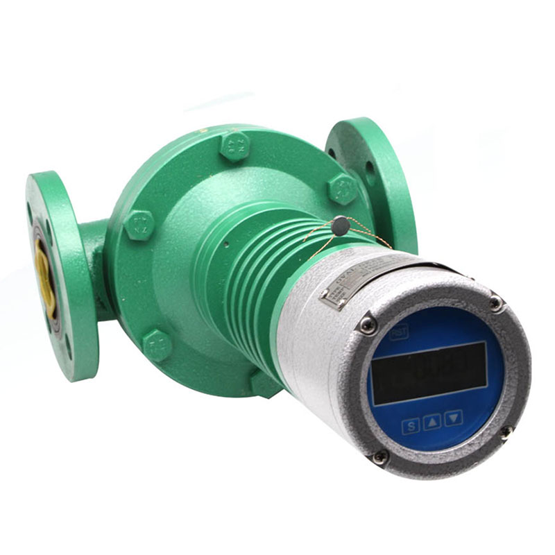
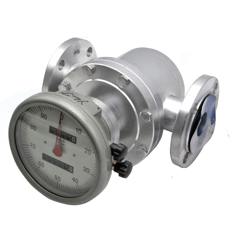
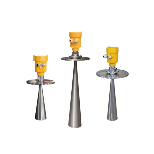
Structure and working principle of Oval Gear Flow Meter
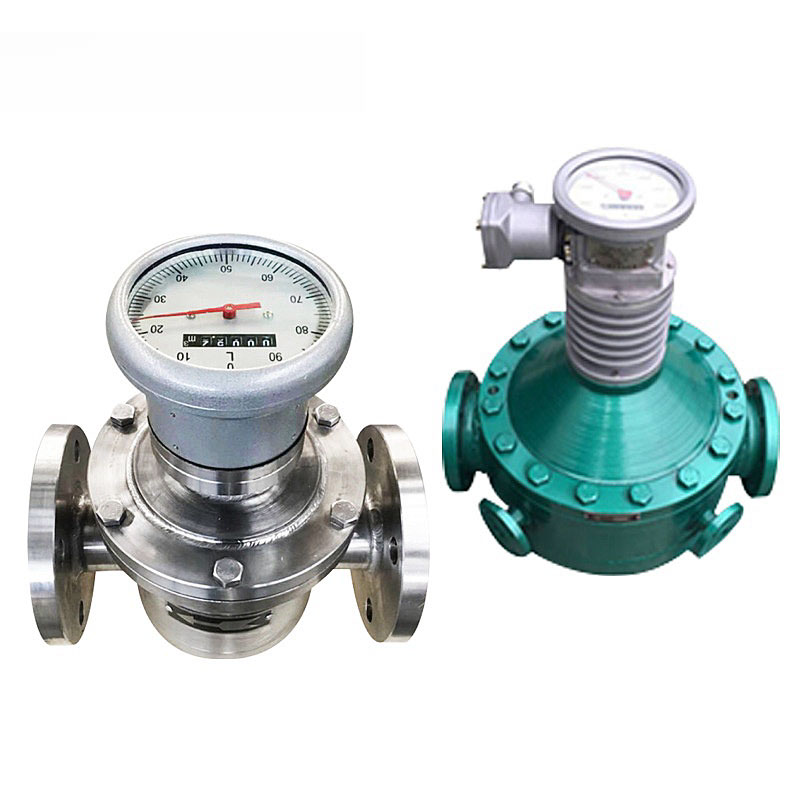
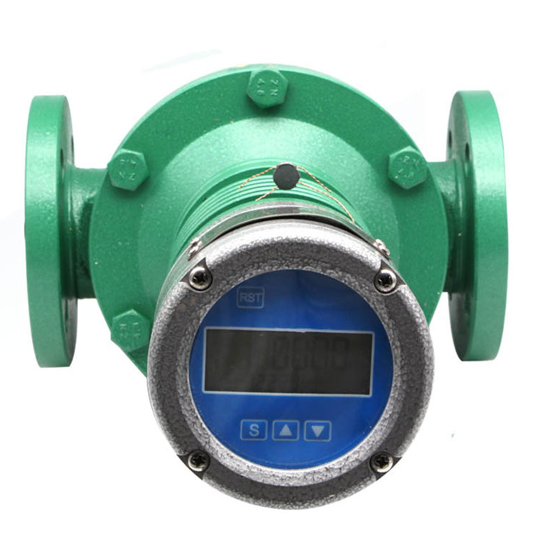
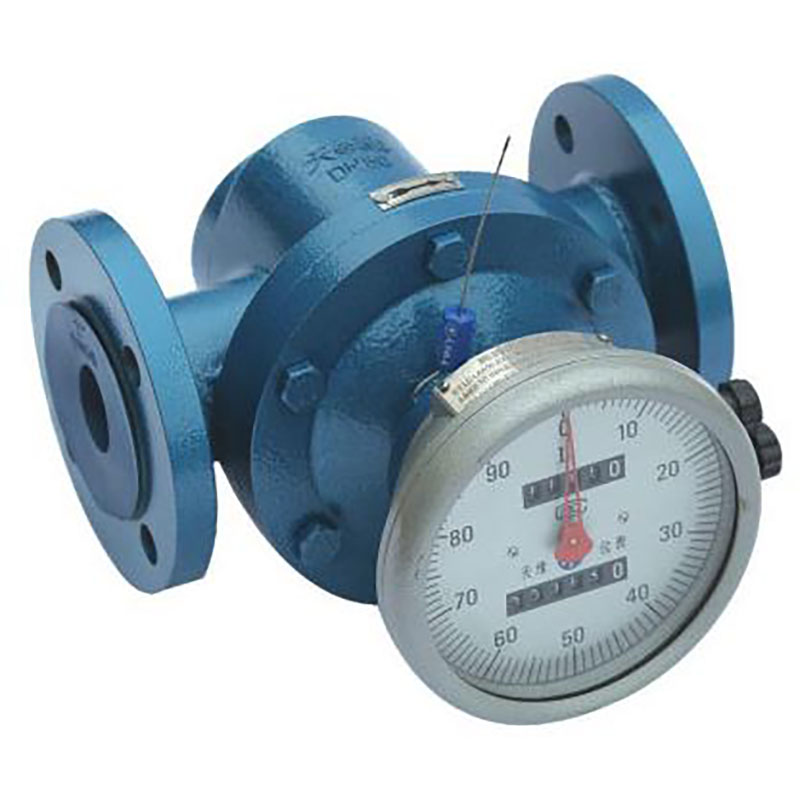
Oval gear flow meter consists of flow transmitter and counting mechanism. A high temperature flowmeter if formed if a radiator is installed between the transmitter and the counting mechanism.
The transmitter consists of a metering chamber and a sealing coupling with a pair of elliptical gear rotors.
The counting mechanism comprises a deceleration mechanism, a regulating mechanism, a counter and a transmitter.
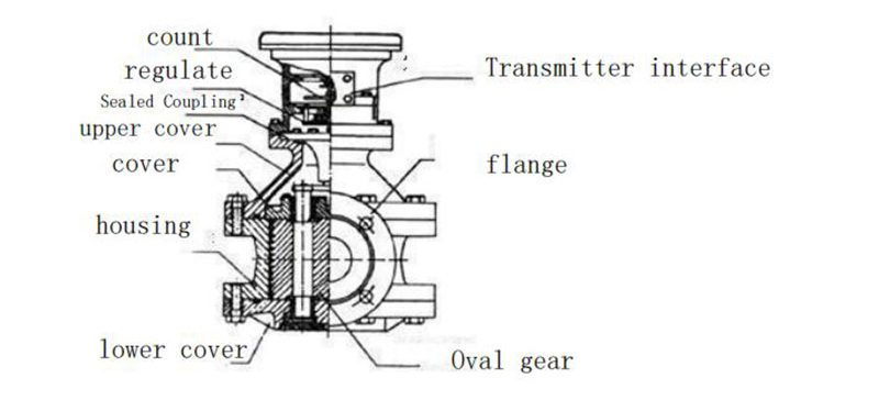
When the measured liquid enters the flowmeter through the pipeline, the pressure difference generated at the inlet and outlet pushes a pair of gears to continuously rotate, and the liquid measured by the crescent-shaped cavity is continuously transported to the outlet. The product of four times the secondary displacement is the total amount of the measured liquid flow.
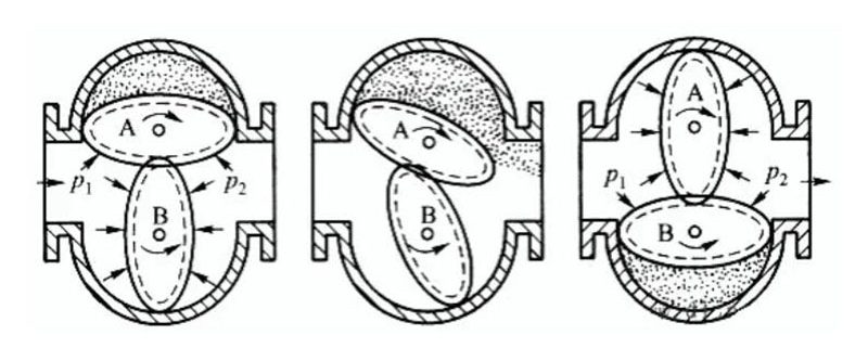
The elliptical gear generates a torque to make it rotate under the action of the pressure difference △p of the measured medium.
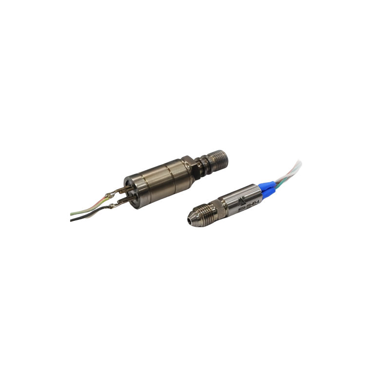
The rotor 1 and the rotor 2 are alternately driven by one to rotate the other. There are two magnets on each rotor as signal generating elements. There is a magnetic signal detecting element at the center of the two axes at the bottom of the cavity. Whenever the magnet turns to the detecting element, the sensor counts as a pulse.
Each pulse corresponds to a certain amount of medium discharge F, F=XXml/p, so the volume flow Qm per unit time can be obtained: Qm=F*H, F is the amount of medium removed by each pulse; H pulse per unit time number.
Installation and Use of Oval Gear Flowmeter
1. A matching filter shall be installed before the flowmeter, and the outlet of the matching filter is connected to the inlet of the flowmeter. The arrow points on both bodies are consistent with the flow direction of the liquid.
2. When the liquid under test contains gas, the gas elimination filter should be installed before the Flowmeter.
3. No matter whether the pipeline is installed vertically or horizontally, the oval gear in the flowmeter shall be installed in a horizontal position (i.e. the gauge disc shall be perpendicular to the ground).
4. When the flowmeter is properly installed, if it is not easy to read, turn the counter to 180 degrees or 90 degrees.
5. The new flowmeter pushes the elliptical gear several times from the exit with a bamboo stick before installation. If it doesn’t move, soak in diesel oil (Avoid sediment after factory check).
6. Flow control valve should be installed at the inlet of the Flowmeter, and open and close valve is installed at the outlet. When using open and close valve, start slowly, do not suddenly open to prevent “water hammer” phenomenon.
7. Before installing the flowmeter on the new pipeline, the pipeline needs to be flushed, and the straight pipe section (instead of the position of the Flowmeter) is used to prevent welding slag, sundries and so on from entering the flowmeter.
8. It is strictly forbidden to check the flowmeter of cast iron and steel with water.
9. The flow size of the flowmeter in use shall not exceed the technical requirements. The flowmeter operates at a maximum flow rate of 50-80%.
10. If the tested liquid is chemically corrosive, a flowmeter of stainless steel should be selected.

