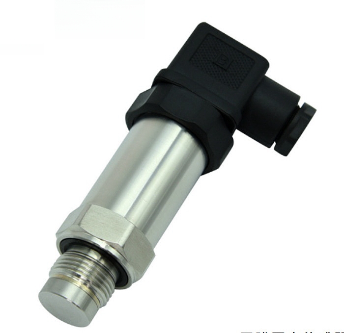
Definition of 4-20mA pressure transmitter
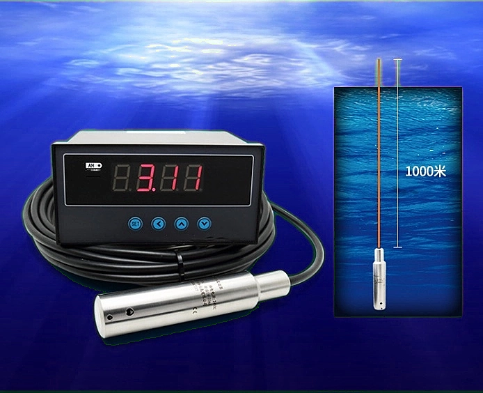
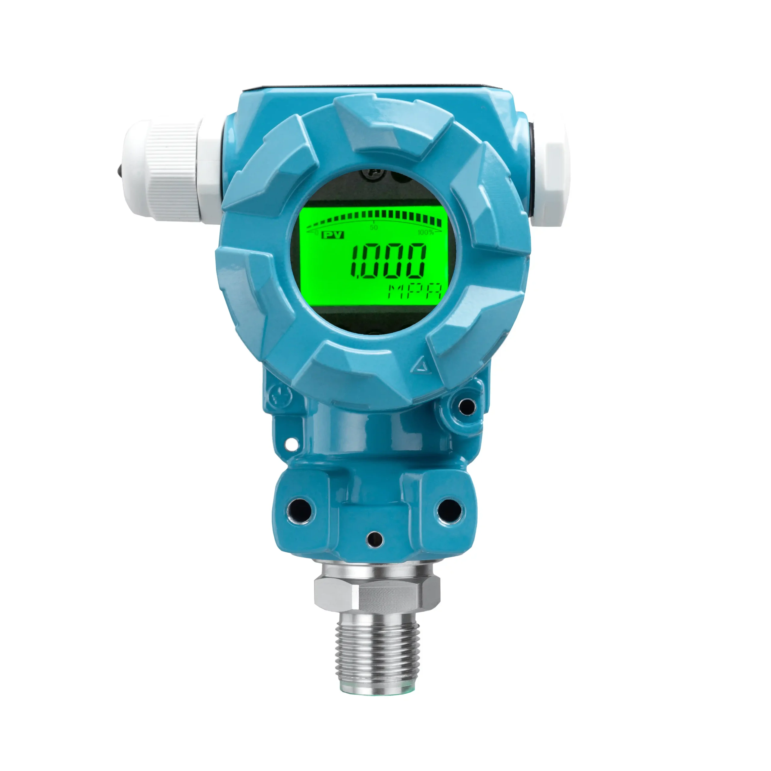
The 4- 20mA pressure transmitter can convert physical quantities into electrical signals. The most widely used method in industry is to use 4~20mA current to transmit analog quantities. As a standard sensor signal converter, the 4- 20mA transmitter can convert analog signals into standard current signals, which is convenient for data collection and processing.
The pressure sensor that outputs 4- 20mA signals is a common industrial automation control component, widely used in petroleum, chemical, electric power, metallurgy, environmental protection and other fields. This article will introduce the circuit principle, application, fault identification and troubleshooting methods of the 4-20mA transmitter in detail.
Principle of 4- 20mA pressure transmitter
Pressure sensors work by sensing pressure and converting it into electrical energy. Piezoresistive, capacitive, and diffused silicon are the most common types used in industrial applications.
The resistance of a piezoresistive material, measured in ohms (Ω), changes when it is stretched or compressed. Piezoresistive pressure sensors consist of a micromachined silicon diaphragm with piezoresistive strain gauges diffused into it. The diaphragm is fused to a silicon or glass backplane. The sensor contains resistors, usually arranged in a Wheatstone bridge circuit. As pressure increases on the piezoresistive material, it offers a greater resistance to the flow of current. This results in an output from the Wheatstone bridge, measured in millivolts, that is proportional to the pressure.
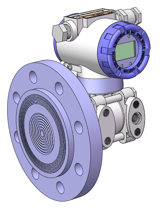
Capacitive pressure sensors use a thin film as one plate of a capacitor. The diaphragm is typically a metal or metal-coated quartz element. One side of the diaphragm is subjected to a reference pressure, and the other side is subjected to the process pressure. Changes in pressure cause slight deformations of the pressure sensing plate, which in turn cause changes in capacitance. These changes in capacitance are proportional to the pressure applied to the plate that is exposed to the process.
The pressure of the measuring medium of the diffused silicon pressure transmitter acts directly on the diaphragm of the sensor (stainless steel or ceramic). This causes the diaphragm to produce a micro-displacement proportional to the medium pressure. Change the resistance value of the sensor. And electronic circuits are used to detect this change. And convert and output a 4- 20mA standard measurement signal corresponding to this pressure.
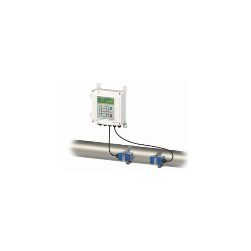
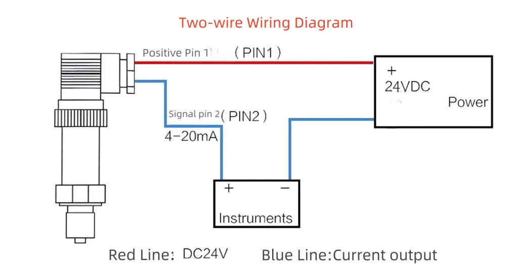
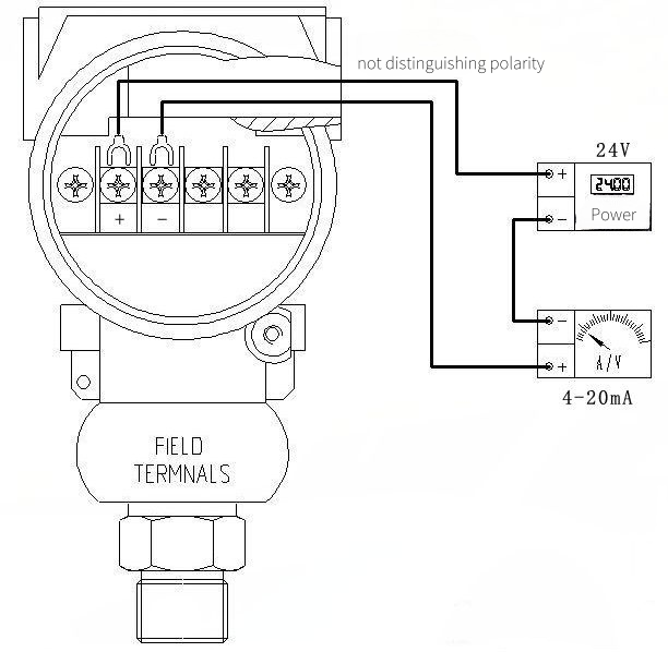
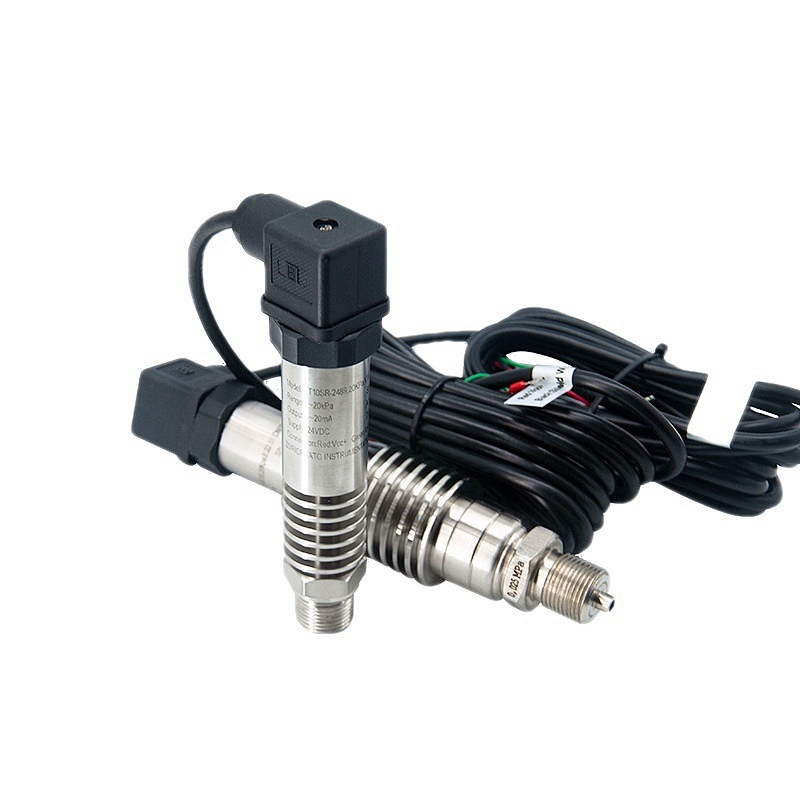
Wiring of a 4- 20mA pressure transmitter
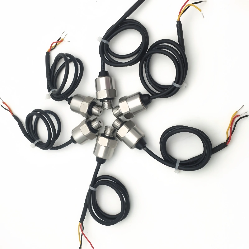
The commonly used model output of our company’s products is two-wire 4- 20mA. There are two diagrams:
Fault detection of 4- 20mA pressure transmitter
Step 1: Check the installation
Most of the pressure transmitter failures are caused by improper use and installation of pressure sensors, which can be summarized in several aspects.
- The primary element (orifice plate, remote measurement joint, etc) is blocked or the installation form is incorrect and the pressure point is unreasonable.
- The pressure pipe leaks or is blocked, there is residual gas in the filling pipe or residual liquid in the filling pipe, and there are sediments in the transmitter process Flange, forming a measurement dead zone.
- The transmitter wiring is incorrect, the power supply voltage is too high or too low, and the connection between the indicator head and the instrument terminal is poor.
- The installation is not strictly following the technical requirements, and the installation method and site environment do not meet the technical requirements.
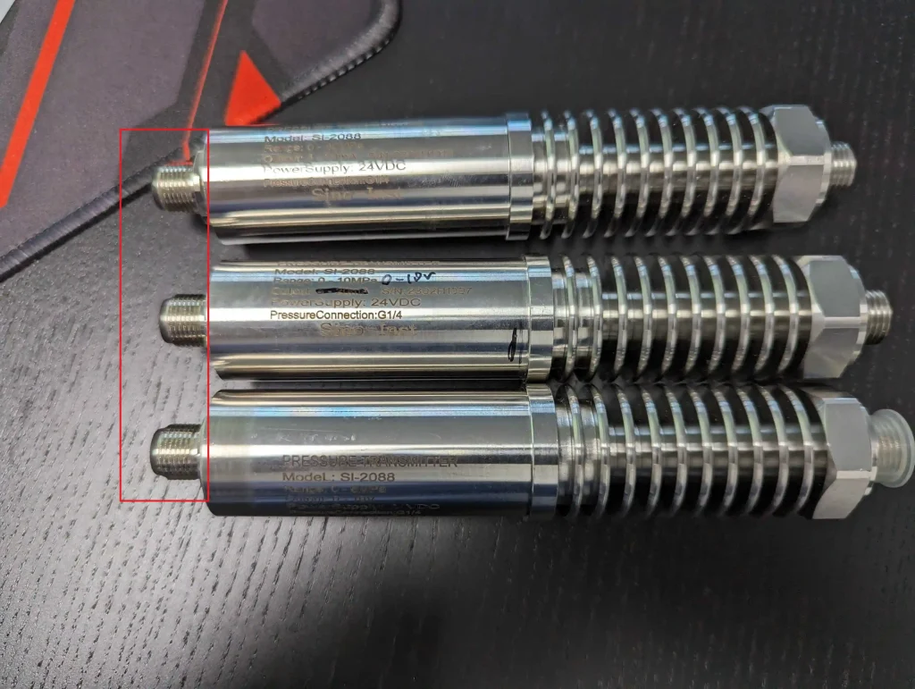
Step 2: Appearance inspection
Check whether the appearance of the sensor is obviously damaged, cracked, or deformed. If damage is found, it may affect the performance and accuracy of the sensor.
- Check the sensor housing
Check whether the housing of the sensor is cracked, deformed or damaged. The integrity of the housing is very important for protecting the internal components of the sensor.
- Check the cable connection
Check whether the cable connection of the sensor is stable, loose or broken. A poor cable connection may cause unstable or distorted signal transmission.
- Check the interface
Check whether the interface of the sensor is clean and whether there is dirt or foreign matter. The cleanliness of the interface is very important to ensure the accuracy of signal transmission.
Step 3: Electrical characteristics test
By testing the output signal, input resistance and other parameters of the sensor, the performance and accuracy of the sensor can be judged.
- Test the output signal
Connect the sensor to the test instrument, set the corresponding pressure value, and observe whether the output signal of the sensor is within the range of 4- 20mA. If the output signal is out of range, it means that there may be a problem with the sensor.
- Test the input resistance
Use a multimeter to measure the input resistance of the sensor, which should generally be between 250Ω-750Ω. If the input resistance is out of this range ,it means that there may be a problem with the sensor.
- Test linearity
Test the output signal of the sensor at different pressures and observe whether the relationship between the output signal and the pressure value is linear. If the linearity is not good, it means that there may be a problem with the accuracy of the sensor.
Step 4: Temperature characteristic test
By testing the performance of the sensor at different temperatures, the stability and reliability of the sensor can be determined.
- Test temperature drift
Place the sensor in different temperature environments and observe whether the output signal of the sensor changes. If the temperature drift is large, it means that there may be problems with the stability of the sensor.
- Test temperature compensation
For sensors with a temperature compensation function, test whether their output signals are consistent at different temperatures. If the temperature compensation effect is not good, it means that there may be problems with the reliability of the sensor.
Step 5: Pressure characteristic test
By testing the output signal of the sensor at different pressures, the accuracy and stability of the sensor can be determined.
- Test the zero point
Place the sensor in a zero pressure environment and observe whether the output signal of the sensor is 4mA. If the zero point deviation is large, it means that there may be problems with the accuracy of the sensor.
- Test range
Place the sensor in the maximum pressure and minimum pressure environments and observe whether the output signals of the sensor are 20mA and 4mA, respectively. If the range deviation is large, it means that there may be problems with the stability of the sensor.
- Test repeatability
Under the same pressure environment, measure the output signal of the sensor multiple times and observe its fluctuation range. If the repeatability is poor, it means that there may be problems with the stability of the sensor.
Step 6: Environmental adaptability test
By testing the performance of the sensor in different environments, the adaptability and reliability of the sensor can be judged.
- Test anti-interference ability
In environments with electromagnetic interference, vibration, etc. test whether the output signal of the sensor is stable. If the anti-interference ability is poor, it means that there may be problems with the reliability of the sensor.
- Test pressure resistance
In a higher-pressure environment, test whether the output signal of the sensor is stable. If the pressure resistance is poor, it means that there may be problems with the adaptability of the sensor.
- Test temperature resistance
In high or low temperature environments, test whether the output signal of the sensor is stable. If the temperature resistance is poor, it means that there may be problems with the adaptability of the sensor.
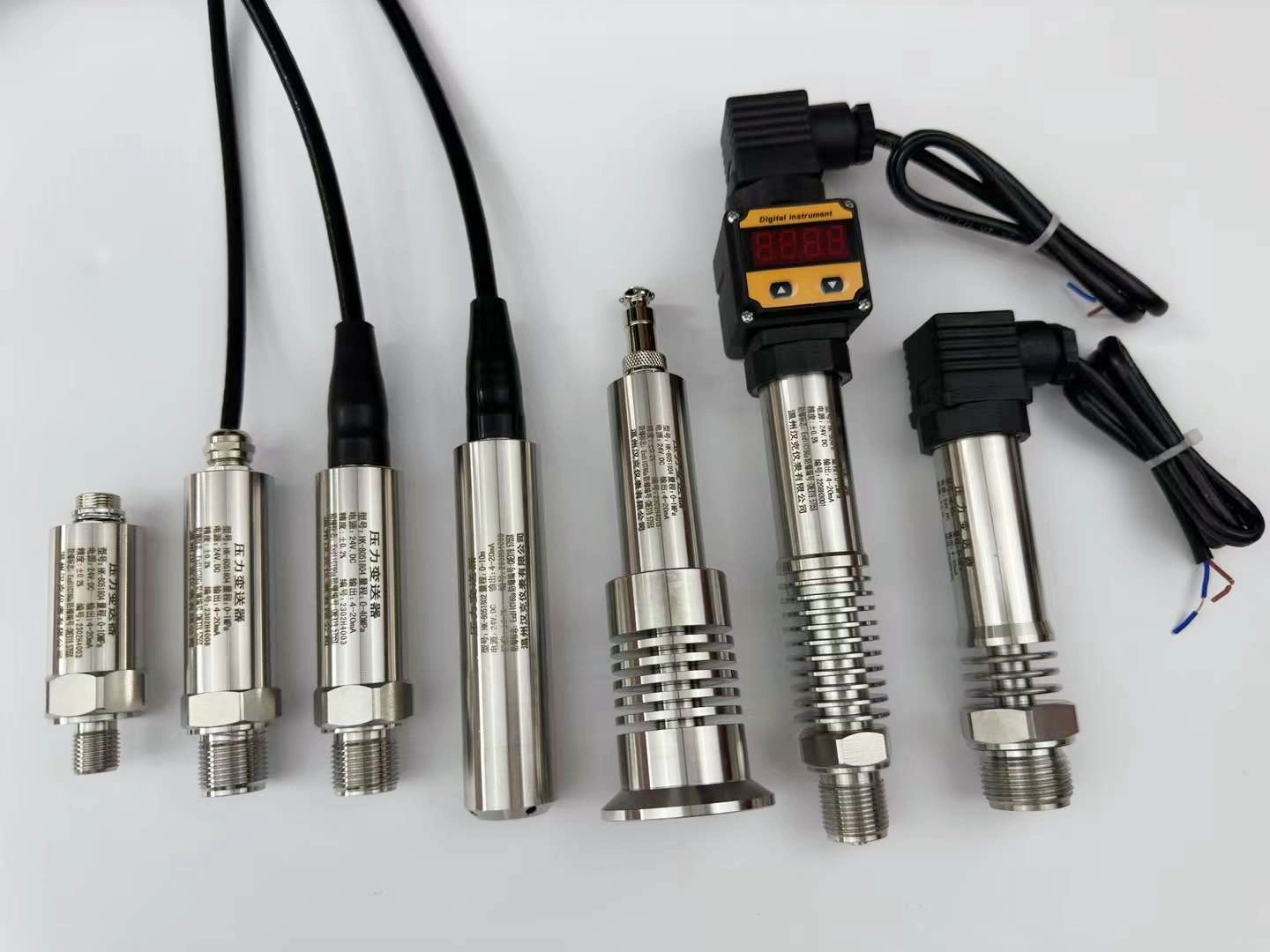
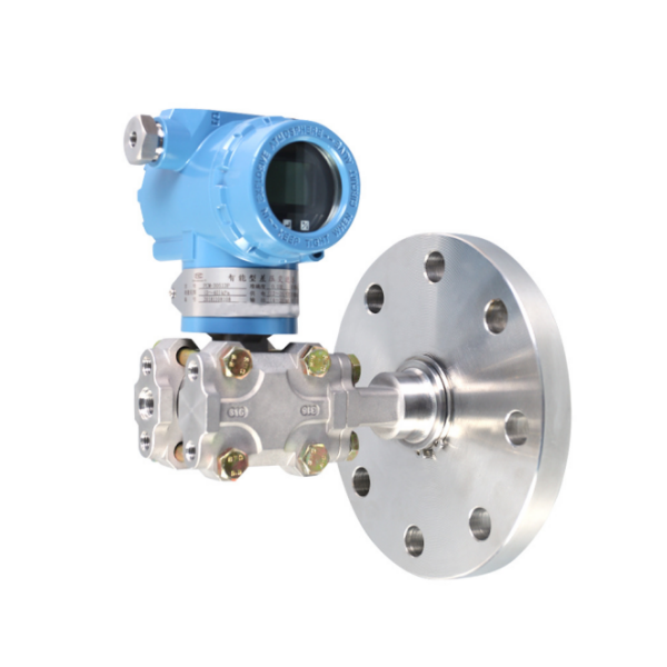
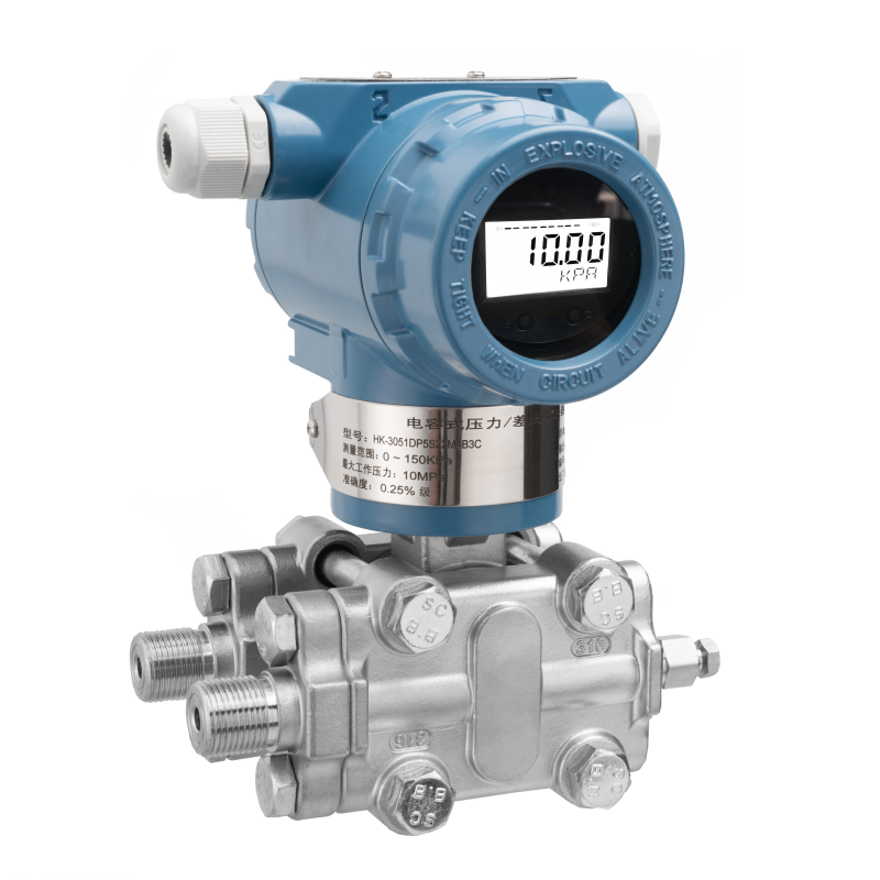
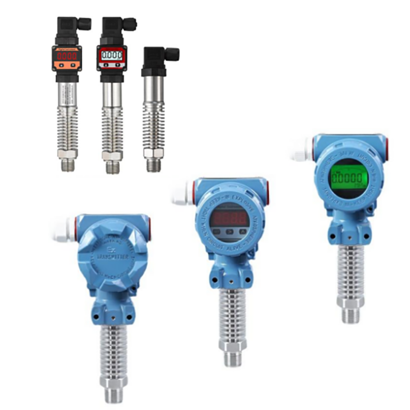
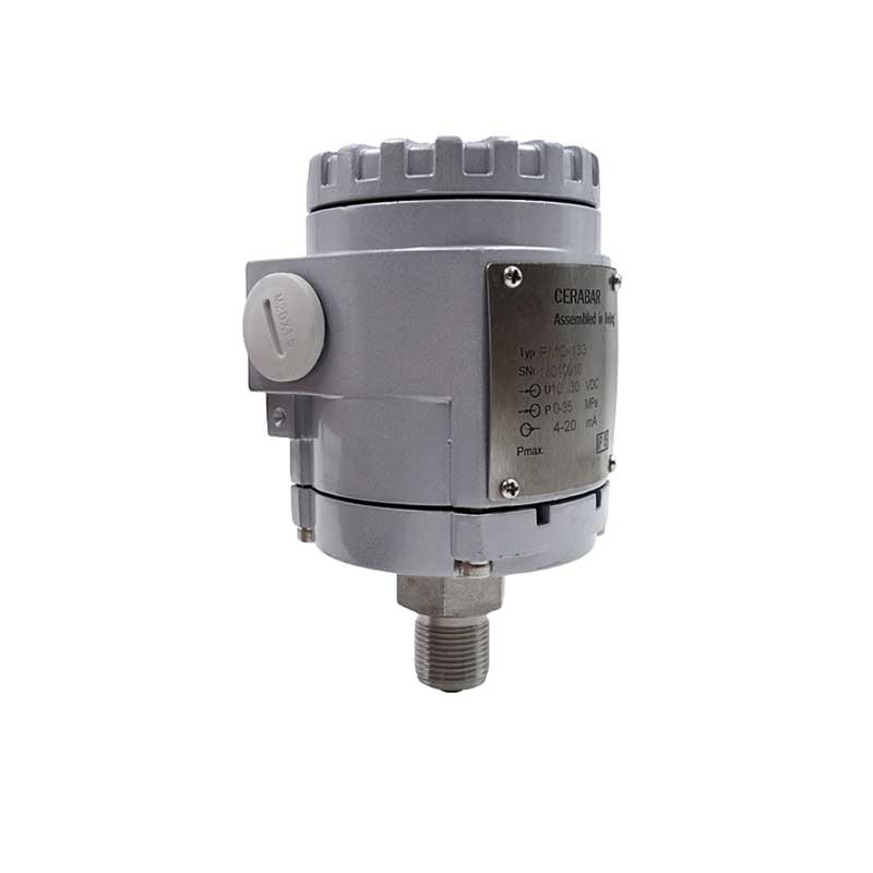
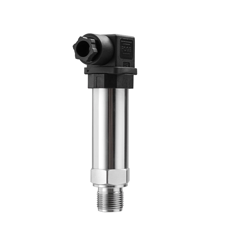
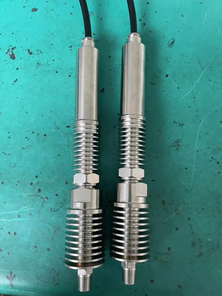
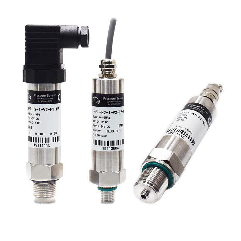
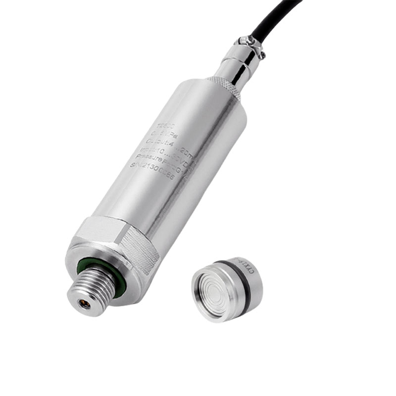
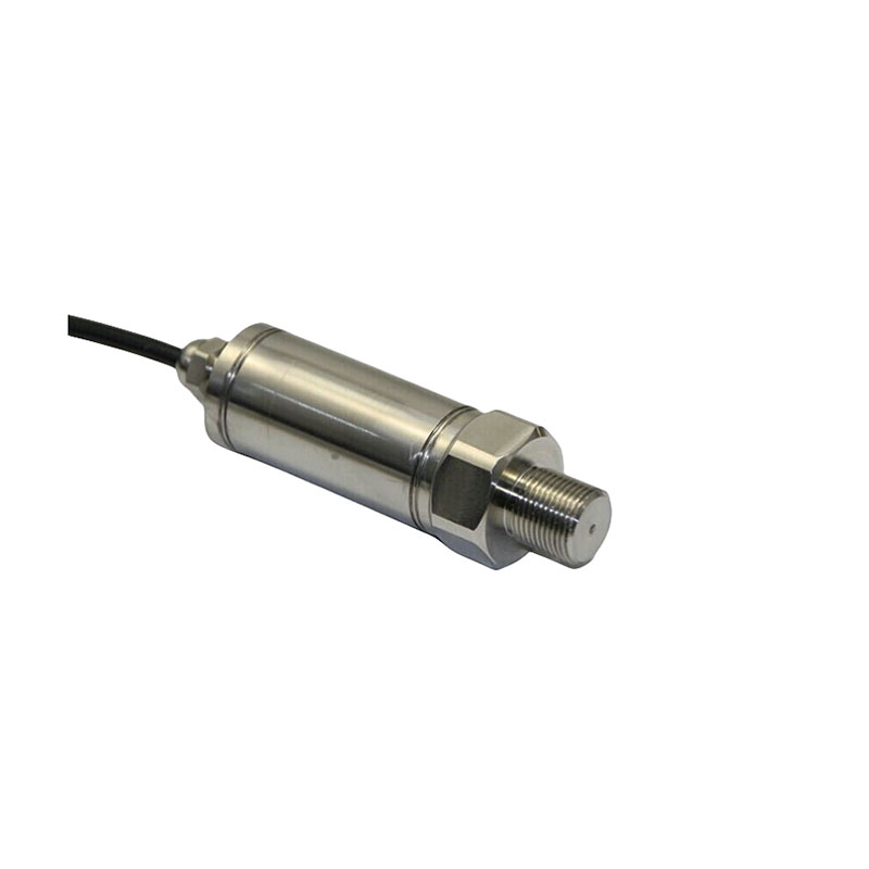
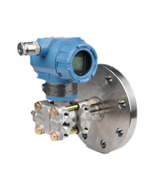
Featured products
Troubleshooting of 4- 20mA pressure transmitter
No current output from the pressure transmitter
- Check whether the power supply of the pressure transmitter is connected in reverse; connect the power supply polarity correctly.
- Measure whether the power supply of the pressure transmitter has a 24V DC voltage; generally, the power supply voltage of the transmitter must be greater than 12V. If there is no power supply, check whether the circuit is disconnected and whether the instrument is selected incorrectly. For example, the input impedance should be less than 250 ohms.
- If it is with a meter head, check whether the meter head is damaged (you can short-circuit the two wires of the meter head first. If it is normal after short-circuiting, it means that the meter head is damaged); if the meter head is damaged, replace it.
- Connect the ammeter in series to the 24V power supply circuit and check whether the current is normal; if it is normal, the transmitter is normal, and other instruments in the circuit should be checked at this time.
- Check whether the power supply is connected to the power input terminal of the transmitter.
The output current of the pressure transmitter is greater than 20mA
- Is the power supply of the pressure transmitter normal? If it is less than 12 volts, check whether there is a large load in the loop, and the input impedance of the transmitter load should meet the requirement that RL is less than the transmitter power supply voltage -12V/20mA ohms.
- Does the actual pressure exceed the selected range of the pressure transmitter? In this case, a pressure transmitter with an appropriate range should be selected again.
- Check whether the pressure sensor is damaged. Severe overload sometimes damages the isolation diaphragm.
- Is the power cord connected correctly? The power cord should be connected to the corresponding terminal.
The output of the pressure transmitter is less than 4mA
- Is the power supply of the transmitter normal? If it is less than 12 volts, check whether there is a large load in the loop, and the input impedance of the transmitter load should meet the requirement that RL is less than the transmitter power supply voltage -12V/20mA ohms.
- Does the actual pressure exceed the selected range of the pressure transmitter? In this case, the pressure transmitter may be damaged. Severe overload sometimes damages the isolation diaphragm.
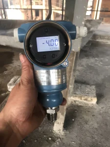
The digital pressure transmitter does not display correctly
- Is the transmitter power supply normal? If it is less than 12V, check whether there is a large load in the circuit. The input impedance of the transmitter load should meet the requirement that RL is less than (transmitter power supply voltage – 12V)/20mA ohms.
- Is the reference pressure value correct? If the reference pressure gauge has low accuracy, replace it with a pressure gauge with higher accuracy.
- Is the range of the pressure indicator consistent with the range of the pressure transmitter? The range of the pressure indicator must be consistent with the range of the pressure transmitter.
- Is the input of the pressure indicator correct with the corresponding wiring? If the input of the pressure indicator is 4- 20mA, the transmitter output signal can be directly connected. If the input of the pressure indicator is 1- 5V,a resistor with an accuracy of one thousandth or more and a resistance of 250 ohms must be connected to the input end of the pressure indicator, and then connected to the input of the transmitter.
- The input impedance of the transmitter load should meet the requirement that RL is less than (transmitter power supply voltage -12V)/20mA ohms; if it does not meet the requirement, corresponding measures can be taken according to the different requirements, such as increasing the power supply voltage (but must be lower than 36V), reducing the load, etc.
- Whether the corresponding equipment housing is wired, the equipment housing is grounded.
- Whether the wiring is separated from the AC power supply and other power supplies; the wiring is separated from the AC power supply and other power supplies.
- Whether the pressure sensor is damaged. Severe overload sometimes damages the isolation diaphragm; it needs to be sent back to the manufacturer for repair.
- Whether there are sand, impurities, etc. blocking the pipeline in the pipeline. If there are impurities, the measurement accuracy will be affected; impurities need to be cleaned and a filter should be added in front of the pressure interface.
- Whether the temperature of the pipeline is too high. The operating temperature of the pressure sensor is -25~85℃, but it is best to be within -20~70℃ in actual use. Add a buffer tube to dissipate heat. It is best to add some cold water to the buffer tube before use to prevent superheated steam from directly impacting the sensor, thereby damaging the sensor or reducing its use.
Through the article, you can solve some fault problems by yourself. If you need more knowledge about a 4- 20mA pressure sensor, please contact us. If you need to buy a pressure sensor. Please contact us! We will provide you with professional answers and services. Sino-Inst is experienced, has a reasonable price and can support OEM. Come and contact us!!!